1
\$\begingroup\$

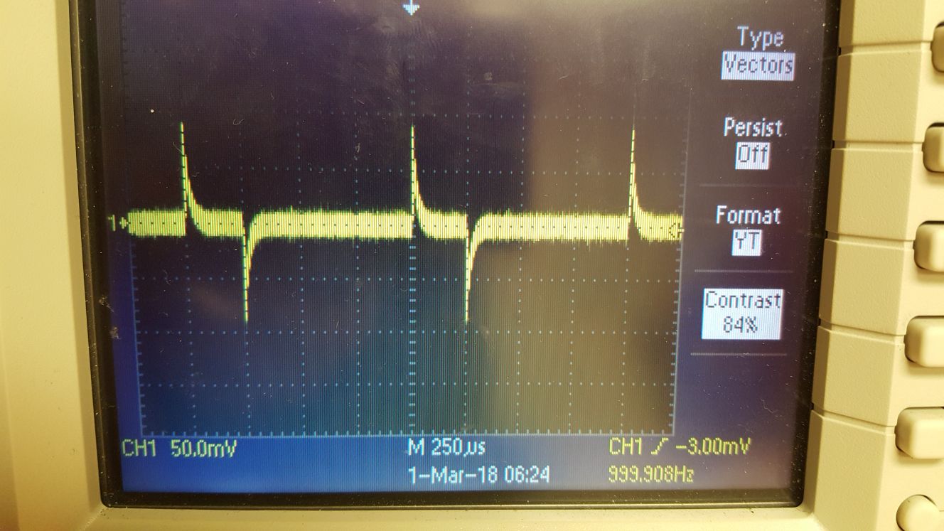
I have a Tektronix TDS 2024B Oscilloscope. For some reason it displays the derivative of the signal. It cannot be the "Math" feature as it only computes addition or subtraction of 2 signals supplied through CH1 and CH2. I even tried to restore the factory settings but it didn't solve the issue either.

Do you have any suggestions on how to make it display the signal itself instead of the derivative?

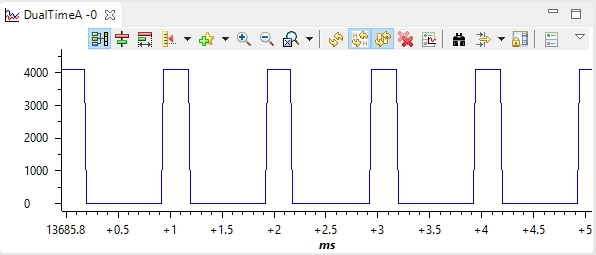
The signal I am supplying: (A square wave with 25% duty cycle.)

enter image description here

The measured signal: enter image description here

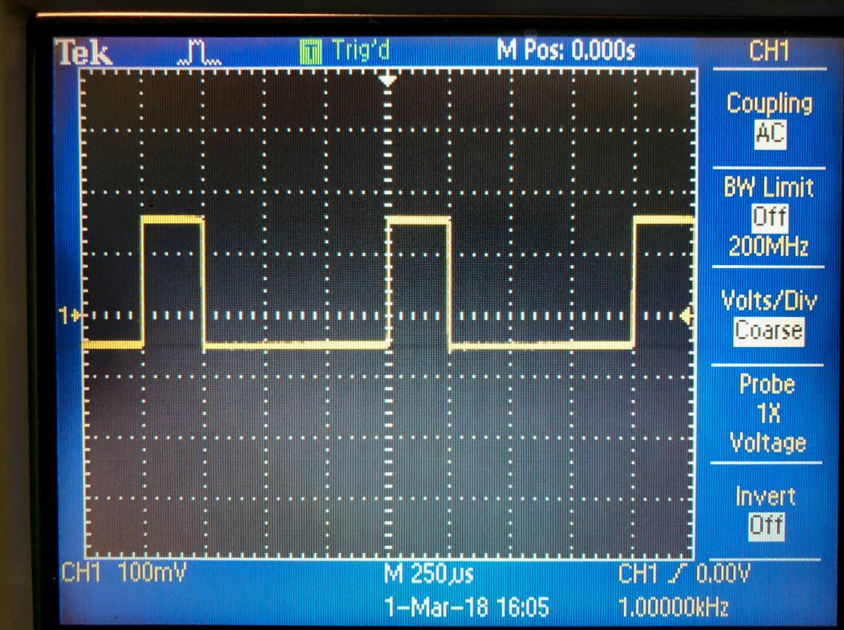
As suggested by Spehro Pefhany I connected the probe to probe comp and this is what I got: enter image description here

Then I did the same with a different probe, and this is what I got: enter image description here
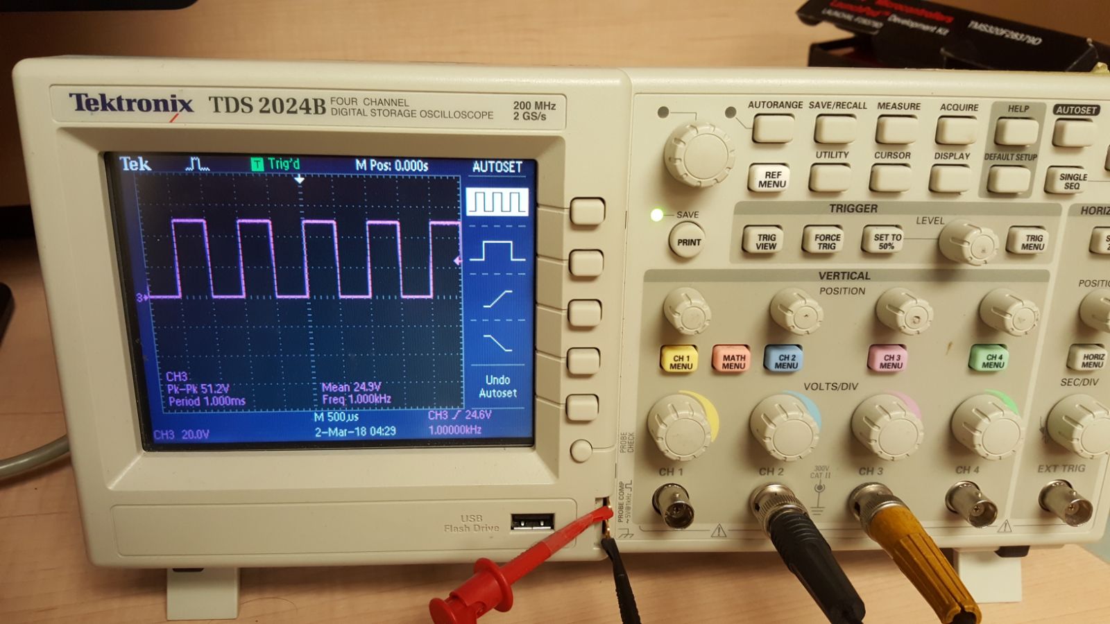
I guess this result validates your hypothesis that the initial probe/cable is broken.

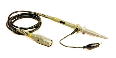
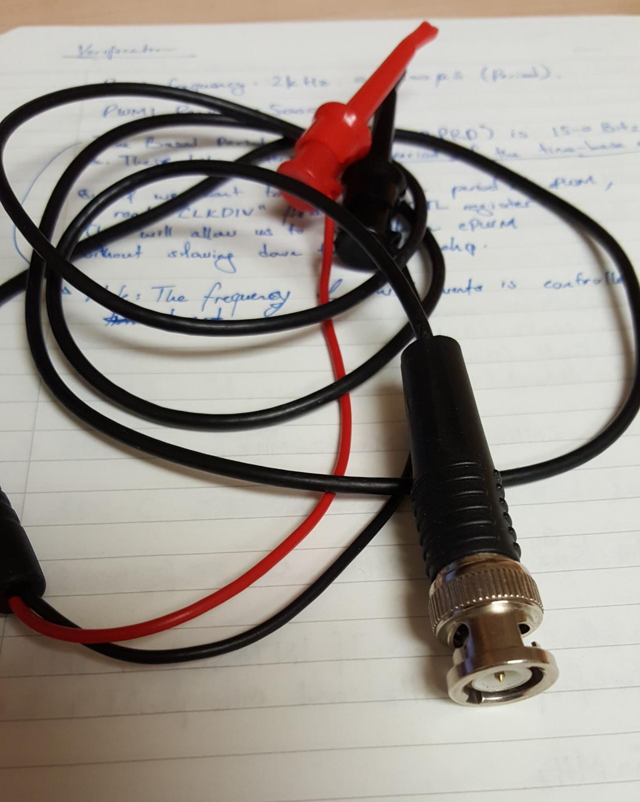
Andre, this is a picture of the initial probe I was using. I am not sure if it has any shielding at all as it is thinner than a regular coaxial cable. Let me know what you think. enter image description here
\$\endgroup\$
10
  • \$\begingroup\$ First of all - how do you know? \$\endgroup\$
    – Eugene Sh.
    Commented Feb 28, 2018 at 20:47
  • 1
    \$\begingroup\$ Adjust the probe compensation? \$\endgroup\$ Commented Feb 28, 2018 at 20:48
  • 9
    \$\begingroup\$ Connect with DC-coupling rather than AC-coupling? \$\endgroup\$
    – glen_geek
    Commented Feb 28, 2018 at 20:50
  • 2
    \$\begingroup\$ Those aren't what you usually call probes. That's a BNC connector with a pair of clips. OK if you are looking at audio signals, not good for anything more demanding. And, not shielded. Probably just a broken wire somewhere. \$\endgroup\$
    – JRE
    Commented Mar 1, 2018 at 19:29
  • 2
    \$\begingroup\$ Buzz it out with a DVM. Probably one side or the other is broken. \$\endgroup\$ Commented Mar 1, 2018 at 21:16

2 Answers 2

8
\$\begingroup\$

Maybe your probe or BNC cable is broken.

Try connecting it to the probe comp input and see what you get. (Connect both the probe and the ground wire to the two lugs). Also try channels 2, 3 or 4 rather than just channel 1.


BTW, the TPS2024 (not TDS2024, which is the one you have) has four completely isolated channels. As such you must connect the ground on each channel you are using to the appropriate spot. Otherwise you could see something much like that. If you are used to 'scopes with a common ground/earth this might be confusing at first, but it is a heck of a useful (and a bit expensive) feature.


Edit: For those who think it possible that setting this scope to AC coupling could produce this waveform, it's true if you don't look at the numbers involved, but not at 250usec/cm sweep. Here is the waveform with AC coupling:

You can see a bit of slope towards zero on the flat portions of the waveform, and it is centered so that the average is 0V, but otherwise it looks pretty much as the DC-coupled waveform would look.

enter image description here

\$\endgroup\$
9
  • 1
    \$\begingroup\$ Yeah. That's not AC coupling or compensation. That's a broken probe ... or cable. UNLESS the source is AC coupled AND you have left the scope input's 50 ohm termination in place. (if the 2024 has that) \$\endgroup\$
    – user16324
    Commented Feb 28, 2018 at 21:08
  • 1
    \$\begingroup\$ Just curious: a broken cable would act as a cable with a series capacitor, right? The armatures being the two sides of the broken conductor, and the dielectric being the thin separation of probe dielectric between the two. It will behave as if the probe were AC coupled. Or is this too simplistic an explanation? \$\endgroup\$ Commented Mar 1, 2018 at 1:20
  • \$\begingroup\$ @SredniVashtar It's completely plausible. Alternatively, connector could be broken. Probes seem to take a lot of abuse (which is one reason why nobody likes lending them). \$\endgroup\$ Commented Mar 1, 2018 at 2:40
  • 1
    \$\begingroup\$ @SpehroPefhany You were right about the probe failure, please check the visuals I have uploaded. \$\endgroup\$
    – csg
    Commented Mar 1, 2018 at 19:03
  • \$\begingroup\$ Downvote because I don't believe for a second you'd get a clear signal like in the OP's picture with a broken probe, especially at such a low frequency. Furthermore, even if the ground wasn't connected, I still wouldn't expect what his picture depicts. It looks like a square wave through an AC coupled input, plain and simple (positive edge of the square wave results in a positive spike, vise-versa for the negative spikes). The fact that it's consistent across pulses highly suggests the cable is not the issue (if it were, I wouldn't expect every pulse to look exactly the same). \$\endgroup\$
    – Shamtam
    Commented Mar 1, 2018 at 20:53
0
\$\begingroup\$

That looks like AC coupling to me. Note that each channel has its own setting for coupling on most scopes. In your first picture, you can see the "Coupling" option in the CH1 menu (that's actually set to AC there). You'll want to check that for whatever channel you're using, you've set the channel to DC coupling if you're trying to probe a square wave.

Also, as mentioned by others, what you're using is not what people would typically call a "probe," as a probe tends to have built-in compensation circuitry. You're simply using a BNC-to-SMD-grabber cable, which doesn't have any compensation built in to correct for the effects of the cable. The following is what people typically refer to as a probe.

An Oscilloscope Probe

\$\endgroup\$

Your Answer

By clicking “Post Your Answer”, you agree to our terms of service and acknowledge you have read our privacy policy.

Not the answer you're looking for? Browse other questions tagged or ask your own question.