0
\$\begingroup\$

I've had success wiring a mechanical CUI encoder according to their datasheet. Values are spot-on for a hardware debouncing and diagram simple to understand for me.

Nevertheless, I prefer for my application a better tactile feedback for the user, so I researched a bit, and it seems like Grayhill 62AG Series would fit perfectly.

Now, looking at their datasheet, I'm surprised how much the wiring changes from the CUI wiring. I suspect this is due to it being an optical encoder vs mechanical to the CUI (?).

Here is the datasheet extract :

Grayhill 62AG Wiring

What is the thing next to the two capacitors ?

What is the LED's purpose between +5V and GND ?

I actually have doubt whether this is the internal wiring of the encoder, or the recommended wiring for it...

\$\endgroup\$
1

2 Answers 2

3
\$\begingroup\$

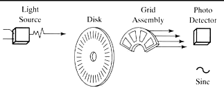
The encoder works by breaking the path of light from the LED, the diode in the encoder to the photo-transistors (the things beside the caps).

A slotted or printed glass disk turns interrupting the light between them.

enter image description here

When lit the transistors turn on, acting sort of like switches.

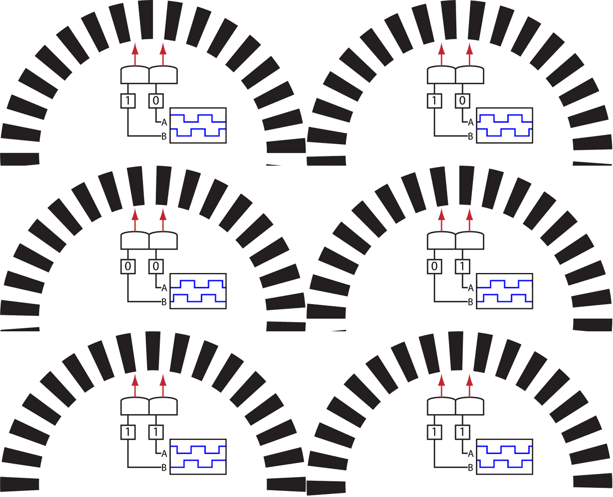
There are two sensors positioned to provide quadrature.

enter image description here

\$\endgroup\$
3
  • \$\begingroup\$ Ok, so I guess this is the internal wiring of the encoder then. I'm confused because they give Resistor and Capacitor values, so I don't know whether I should put those on my board, or if they are already contained within the device and the whole encoder is more like plug-as-is. Would a standard RC filter (like for the CUI encoder) be required for optical encoders ? \$\endgroup\$
    – Fredovsky
    Commented Mar 5, 2018 at 20:53
  • \$\begingroup\$ The things to the right of the numbers are internal. To the left - external. \$\endgroup\$
    – Eugene Sh.
    Commented Mar 5, 2018 at 20:56
  • 1
    \$\begingroup\$ @Fredovsky the circuitry on the right of the connector circles is internal. The circuit on the left Is what you need to use.. Assuming you use the same voltage supply, 5V, if not you may need to adjust the values. \$\endgroup\$
    – Trevor_G
    Commented Mar 5, 2018 at 20:57
0
\$\begingroup\$

Your connections for ABC = pins 145 or 154 depending matching or reversed rotation.

Pin 6 is for LED current and pullup R's to 5V with return on pin 1.

Pin 2,3 are optional extra momentary NO switch

RC addon is optional as the optical encoder uses Grey Code which is more immune to transition bounce especially with optical path detection like a mouse wheel. So you can leave out.

\$\endgroup\$

Your Answer

By clicking “Post Your Answer”, you agree to our terms of service and acknowledge you have read our privacy policy.

Not the answer you're looking for? Browse other questions tagged or ask your own question.