0
\$\begingroup\$

I'm currently working on my very first SMT PCB, and would like to connect a number of PCBs to the main PCB using spring loaded pogo pins like these:
http://uk.farnell.com/harwin/p19-2221/probe-convex-1-90mm-pitch/dp/9960171

My question is in 2 parts:

1)

What kind of connection would you use for the 'female'?
I wanted to use some small pads like the ones shown here: https://www.harwin.com/product-highlights/pogo-pins-pads/ Somebody suggested leaving plated through holes where the pins would connect but I am skeptical about the long term durability of this method.

2) How would I best go about implementing that type of connection on an eagle schematic / PCB?

Must add that I do not literally mean those exact products, just included the links as an example

\$\endgroup\$
4
  • 1
    \$\begingroup\$ Not sure if I got your question, 1) would be a plated exposed pad (through hole is arguable for aligning, but I use other holes for alignment), and 2) just draw an exposed pad in eagle and have your PCB plated. Is that it? \$\endgroup\$
    – Wesley Lee
    Commented Mar 6, 2018 at 15:01
  • \$\begingroup\$ Yeah that's what I was thinking, just wondered if anyone had any special trickery that would be of use :) \$\endgroup\$
    – GigaJoules
    Commented Mar 6, 2018 at 15:26
  • \$\begingroup\$ It sounds like this is for use rather than a test fixture so you might want to also look at things like traditional stacking board to board connectors, standard size flex ribbons, or even zebra strips. \$\endgroup\$ Commented Mar 6, 2018 at 16:27
  • \$\begingroup\$ The problem is that I want something that the user can quickly connect and disconnect, whilst being able to produce a socket that allows the module placed in it to rotated by 90 degrees so soft connections are out out the question as there are 64 sockets involved! \$\endgroup\$
    – GigaJoules
    Commented Mar 6, 2018 at 16:31

3 Answers 3

3
\$\begingroup\$

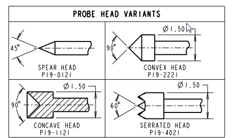
That kind of pogo pin is designed to contact the inside of a plated-through hole. So a hole that takes you about halfway down the cone would make sense. The cone is 1.5mm diameter so a 1.0 to 1.2mm hole, with a pad that at least meets the minimum annular ring specification of your PCB maker.

There are other variants of probe heads. The serrated head is designed to contact a pad. The concave head goes over a pin or clipped (but not cinched) lead wire.

enter image description here

This should be fine for testing or programming, however the pressure may not be high enough to ensure long-term reliability if you intend it as a "permanent" connection.

\$\endgroup\$
5
  • \$\begingroup\$ Sorry didn't mean to edit. I'm not necessarily set on that type of head. What I intend to do is have a pair of small Neodymium magnets between the PCBS (Raised away from the board with a 3d printed structure) and use them to maintain pressure against the main board. Very helpful answer though, thanks. It's quite likely that the top PCB will get prodded pretty hard by the user. Which connection would you recommend? \$\endgroup\$
    – GigaJoules
    Commented Mar 6, 2018 at 15:25
  • 2
    \$\begingroup\$ You mean the user can push the pogo pins down? If that's an issue simply put something in there that limits the range of motion so it's well within the compliance range of the pin. \$\endgroup\$ Commented Mar 6, 2018 at 15:27
  • \$\begingroup\$ AH of course! It'll do that anyway! It's too easy to get lost in the system design and forget about the rest of the mechanics! \$\endgroup\$
    – GigaJoules
    Commented Mar 6, 2018 at 15:33
  • \$\begingroup\$ My impression is that the spring pins intended for permanent application are different than these test ones - typically shorter, with a larger diameter housing and less dense positioning. A need for dense interconnect in the operation of a product probably suggests a different technology than spring pins. \$\endgroup\$ Commented Mar 6, 2018 at 16:28
  • \$\begingroup\$ Yes, I'm looking for a permanent solution that is appropriate for the end user. \$\endgroup\$
    – GigaJoules
    Commented Mar 6, 2018 at 16:34
2
\$\begingroup\$

There are pogo pins for more permanent usage, usually, they have either flat or domed tips. The serrated and sharp variants are used to pierce flux residue.

As for the receiving side, a pad usually does the trick, however, if your PCB surface plating is prone to oxidation, you can use selective gold plating on those pads.

\$\endgroup\$
1
\$\begingroup\$

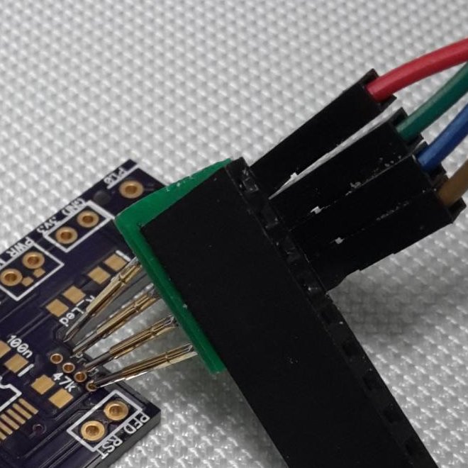
For temporary connection (test points for signal checking or flashing microcontroler) I am using similar connection to this one...

enter image description here

but in my case pins are on the right angle related to PCB and they are going going inside PCB.

However, for permanent connection I am using low profile female (individual) pin sockets.

\$\endgroup\$
2
  • \$\begingroup\$ Would you mind pointing me in the direction of the pin sockets you're using? I was using basic male / Female headers in my initial prototype (only had a couple of hundred £'s to spend and about 700 points to connect). I found that they were a little too fragile for me and didn't align very nicely but they were only basic and cheap. \$\endgroup\$
    – GigaJoules
    Commented Mar 6, 2018 at 15:40
  • 1
    \$\begingroup\$ In my case I need just few of them, so price was not a issue. I used samtec SL-132-G-19 (newark.com/samtec/sl-132-g-19/socket-strip-2-54mm-through-hole/…), individual sockets with removed plastic. \$\endgroup\$
    – josip
    Commented Mar 6, 2018 at 15:55

Your Answer

By clicking “Post Your Answer”, you agree to our terms of service and acknowledge you have read our privacy policy.

Not the answer you're looking for? Browse other questions tagged or ask your own question.