7
\$\begingroup\$

The theory says that the current return path at high frequency is on the reference plane right under(or above) the signal trace.

I know it is true and I have always assumed it was, but I would like to understand it properly.

My trouble is about it can be power or gnd plane for the reference plane.

If we use a 6 layer stackup:

Signal

GND Plane

Signal

Signal

PWR plane

Signal

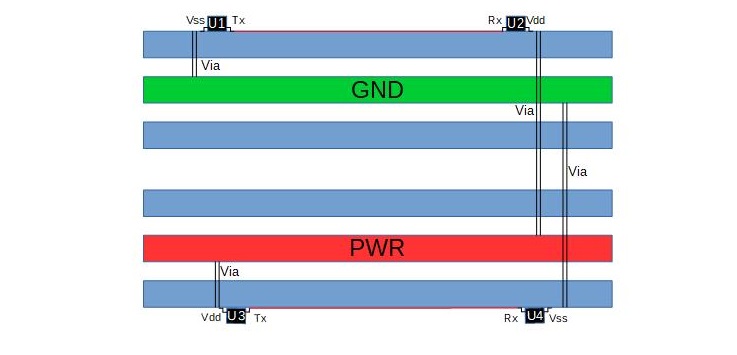
If we take the example of two device U3 and U4 on Bottom layer (referenced to a Vdd power plan), with U3 having a Tx pin connected to a Rx pin on U4: When U3 output a 1 the current goes:

Power Vdd=>U3 Vdd pin=>U3 Tx pin=> U4 Rx Pin=> U4 Vss Pin=> and then?

How is the current passing from U4 Vss pin to Vdd power plan? Capacitor? Because there is no connection as you can see in the picture/

Also wy is the current not flowing to the GND plan? Is the inductance created by going to the GND Plan that much bigger than the one created by going to the Vdd Plan?

Now if we take the same example but on Top layer( referenced to a ground plane):

When U1 output a 0 am I right to assume the current goes:

Power Gnd=>U1 Vss pin=>U1 Tx pin=> U2 Rx Pin=> U2 VddPin=> again and then?

How is the current passing from U2 Vdd pin to Gnd power plan? Capacitor?

Also why is the current not flowing to the Vdd plan? Is the inductance created by going to the Vdd Plan that much bigger than the one created by going to the Vdd Plan?

Another question related to the answer is, what if the reference power plane is not of the same voltage as U1 and U2 power voltage? Is that still working as a power reference plane?

Edit: Here is a drawing of the stack up and components I am talking about for clarification: enter image description here
\$\endgroup\$
3
  • 5
    \$\begingroup\$ Draw a picture; don't use ambiguous words. \$\endgroup\$
    – Andy aka
    Commented Mar 8, 2018 at 12:02
  • 5
    \$\begingroup\$ Yes, please do. I Started to read this and gave up half way. Potentially interesting question with potentially interesting answers, but incomprehensible as it is right now. \$\endgroup\$
    – gommer
    Commented Mar 8, 2018 at 12:06
  • \$\begingroup\$ I did, is it better? \$\endgroup\$
    – damien
    Commented Mar 14, 2018 at 10:57

1 Answer 1

13
\$\begingroup\$

The theory says that the current return path at high frequency is on the reference plane right under(or above) the signal trace. I know it is true and I have always assumed it was, but I would like to understand it properly.

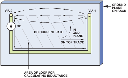
There are far too many ambiguous words describing your scenarios so draw a picture but, in the meantime consider what happens when you have a DC return current in a ground plane: -

enter image description here

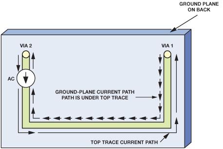
The path taken by the DC is the path of least resistance hence DC favours the direct route from via 1 to via 2. For AC you have to consider that the path for a return current is both the path of least resistance AND the path of least reactance. The path of least reactance is the path of least inductance: - enter image description here

So, to minimize the inductive loop (and the impedance it might present), AC current will take the path of least inductance and that is directly underneath the top trace that carries the forward current.

Picture source

\$\endgroup\$
5
  • \$\begingroup\$ I added a drawing for clarification. But I understand the theory that the current go through the path with the smallest inductance the question is how does it jump from the Vss pin to the PWR plane because it has to pass by somewhere. How bigger is the loop to go the GND plane compared to this jump by I do not know where. \$\endgroup\$
    – damien
    Commented Mar 14, 2018 at 10:56
  • \$\begingroup\$ All chips must have GND and Vcc connections to ground planes and power planes. Your diagram doesn't seem to show that. All chips in a situation like this should have supply decouplers. Your diagram doesn't appear to show this. GP and PP are capacitively coupled naturally plus, add on all the decouplers and PP and GP share AC signal currents (irrespective of DC voltage differences). \$\endgroup\$
    – Andy aka
    Commented Mar 14, 2018 at 11:09
  • \$\begingroup\$ Obviously they have both connections GND and Vcc but the current in U4 flows from Rx to GND pin not Vdd pin. And the second part is exactly my question does the current path by the decoupling capacitor? Because if it does, it means the inductance of the capacitor is smaller than the inductance of the loop created if you go to the GND plane \$\endgroup\$
    – damien
    Commented Mar 14, 2018 at 13:17
  • \$\begingroup\$ Do you mean "the impedance of the capacitor"? \$\endgroup\$
    – Andy aka
    Commented Mar 14, 2018 at 13:19
  • \$\begingroup\$ Yes, my trouble is if from the Vss pin it goes through the capacitor then to the PWR plane it means that the (impedance of the capacitor + impedance of the loop created on the PWR plane)<impedance of the loop created by going directly to the GND plane \$\endgroup\$
    – damien
    Commented Mar 15, 2018 at 14:26

Your Answer

By clicking “Post Your Answer”, you agree to our terms of service and acknowledge you have read our privacy policy.

Not the answer you're looking for? Browse other questions tagged or ask your own question.