3
\$\begingroup\$

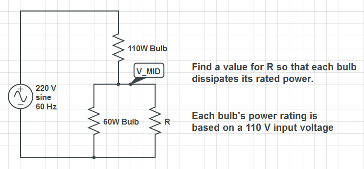
I have a bulb rated 110 V, 60 W and is in series with another bulb which is 110 V, 110 W. It's being powered with a 220 V source. Now, what would be the resistance of the resistor to be added in parallel to the first bulb so that each bulb will get the rated power?

The way I approached this is first get the resistance of each bulb, then get the voltage drop of each bulb via current divider principle. After that, I'm stuck.

enter image description here

\$\endgroup\$
2
  • \$\begingroup\$ I'm curious how you got to the 302.5Ω \$\endgroup\$
    – jippie
    Commented Jul 19, 2012 at 9:34
  • \$\begingroup\$ My bad, the 110 w should be 100 w. anyways solutions are correct \$\endgroup\$ Commented Jul 19, 2012 at 10:47

4 Answers 4

5
\$\begingroup\$

As Steven states, this is only true when the bulbs act like ordinary resistors.

The solution is easy. The voltage across the 'divider' will be evenly distributed when power at the top half and power at the bottom half are equal.

  • Power at the top half is 60W.
  • Power at the lower half is 110W.

To have equal power both at top and at bottom halves, you have to add an extra \$110W - 60W = 50W\$ in parallel to the existing top bulb.

Ohms law:

\$R = \dfrac{U}{I}\$

and

\$I = \dfrac{P}{U}\$

Substituting the second equation into the first, gives us the familiar: \$R = \dfrac{U^2}{P}\$

Now fill in the details:

\$R = \dfrac{U^2}{P} = \dfrac{(110 V)^2}{50W} = 242 \Omega\$

\$\endgroup\$
5
  • 1
    \$\begingroup\$ +1. A nice and elegant variation that shows how multiple approaches lead to equally good results. \$\endgroup\$
    – zebonaut
    Commented Jul 19, 2012 at 9:19
  • \$\begingroup\$ @zebonaut - and fortunately the same result :-) \$\endgroup\$
    – stevenvh
    Commented Jul 20, 2012 at 5:12
  • \$\begingroup\$ My question is did you realize you were burning the 60W bulb hotter than rated? and that running in parallel on 220V line would really make them fail quickly. YOu cannot run 2 different Watt rated bulbs in series at twice the rated voltage. One the lower power will have a larger voltage drop than rated and burn out faster. Since they share current, they will tend to run closer to similar power dissipation except the 60W bulb has a thinner filament and will run hotter. so"Power at the top half is 60W. Power at the lower half is 100W." is a false assumption. \$\endgroup\$
    – D.A.S.
    Commented Jul 20, 2012 at 19:01
  • \$\begingroup\$ Also the cold resistance is ~ 10% of hot resistance. so with contact bounce, you can expect the 60W bulb to get hot faster while the 100W bulb is slower in heating up since less than rated current and in equilibrium gets only 60/160 or 3/8 of the voltage (37.5%) and even less power. Proof is elementary. \$\endgroup\$
    – D.A.S.
    Commented Jul 20, 2012 at 19:09
  • 1
    \$\begingroup\$ @TonyStewart, try rereading the question. I think you're missing some details about the circuit from the original question. I will go ahead and draw a schematic since this is causing confusion. I agree that lightbulb thermal dynamics would probably cause issues if this was a real circuit, but it seems much more like a theoretical/homework question. \$\endgroup\$
    – W5VO
    Commented Jul 20, 2012 at 23:10
10
\$\begingroup\$

I'll presume your bulbs are ordinary resistors first. The 60 W bulb is R1, the other one R2.

Resistance can be calculated as

\$ R = \dfrac{V^2}{W} \$

For R1 and R2 that's

\$ R1 = \dfrac{(110 V)^2}{60 W} = 202 \Omega \$

\$ R2 = \dfrac{(110 V)^2}{110 W} = 110 \Omega \$

Then Rp || R1 = R2, or

\$\dfrac{Rp \cdot R1}{Rp + R1} = R2 \$

Filling in the values gives

\$\dfrac{Rp \cdot 202 \Omega}{Rp + 202 \Omega} = 110 \Omega \$

Solving for Rp gives us 242 Ω.

That would it be if the bulbs were ordinary resistors. They're not they're PTC resistors with a very low resistance at room temperature, and higher when the filament is heated by the current. Operating them at lower voltages by placing two of them in series will decrease the resistance, but you'll have to measure the voltage across each of them ,and the current to know what the resistance at that voltage is. So for the bulbs there's no easy answer.

\$\endgroup\$
1
  • 4
    \$\begingroup\$ @Downvoter - Please tell us what's wrong with this answer. \$\endgroup\$
    – stevenvh
    Commented Jul 21, 2012 at 12:58
1
\$\begingroup\$

This looks like a homework problem, so I'll give some hints and let you do the math.

You want the voltage to be equal on both bulbs. Therefore, neglecting the thermal influence on the bulbs' resistances1), you need to decrease the resistance of the bulb with the lower power rating (60 W) such that it is equal to the resistance to the bulb with the higher power rating (110 W). This way, you get a voltage divider with two equal resistances R1 and R2, equally sharing the provided voltage of 220 V, with R1 being the parallel resistance of the 60 W bulb and your additional resistor, R2 being the resistance of the 110 W bulb.

Step 1: Using the ratings of the "brighter bulb", solve for its resistance.

Step 2: Do the same for the not-so-bright bulb.

Step 3: Using the formula for parallel resistances, determine the resistor needed in parallel with the other bulb.

Step 4: Upon successful accomplishment, you'll look like a very bright bulb.


1) Thermal variation of the bulbs' resistances is often neglected in homework problems, so I guess this is a safe simplification to do.

\$\endgroup\$
2
  • \$\begingroup\$ Not only a bad assumption but it useful to remember tungsten resistors are PTC 1:10 ratio from off:on. \$\endgroup\$
    – D.A.S.
    Commented Jul 20, 2012 at 22:46
  • \$\begingroup\$ @TonyStewart Well, in the first place (before worries about tempco): No one would waste 50 W using a parallel resistor in the real world to make such a circuit work. As I said: Safe to assume this is a not-so-practical example from an 8th grade physics book. No offense against 8th graders, but big offense towards some of the nuances how physics are taught in school. \$\endgroup\$
    – zebonaut
    Commented Jul 21, 2012 at 17:54
-1
\$\begingroup\$

There is a problem with the assumptions all the other answers that series connected bulbs will draw the same current. This is incorrect and both bulbs must be equal rating for this to to work.

As "@stevenh" reports correctly. tungsten light bulbs are PTCs with a cold surge current ratio of 10:1 worst case which corresponds to the resistance ratio when hot.

Ref: R ratio for tungsten R/R300= 10.30 with temp rise = 1800 C so using 10.3 below with corrected resistance values for 100W bulb by user in latter remark at 110V we get;

\$ R = \dfrac{V^2}{W} \$

for 60W, R = 202 Ω hot, R/10.3 = 19.6 Ω at room temp. where currents are 0.54A, 5.6A, respectively.

for 100W, R = 121 Ω hot, R/10.3 = 11.7 Ω at room temp, where currents are 0.91A, 9.4A, respectively.

The series voltage divider ratio at room temp is,

For 60W bulb 19.6 / ( 19.6+10.3) * 220Vrms = 144Vrms or 144^2/19.6Ω = 1,058 W Current is then 144Vrms/ 19.6Ω = 7.3A at power on @ room temp. ( averaged over 1 cycle)

Note that this is 7.3/5.6 = 1.30 or 30% over voltage and significantly over-power rating.

This will lead to **P.O.O.F.**  or "Premature Optical Ocular Failure" ™ j/k ;)

More proof is elementary. Running in parallel at 220V would be even fast Poof and runing in parallel at 110 is light how light bulbs are normally used.

Is there a point to this futile experiment? Unless you are trying to design a constant current load with PTC on a 50V DC circuit or similar, Please advise at your earliest convenience. Tony.
\$\endgroup\$
8
  • 2
    \$\begingroup\$ It's a homework problem (which the OP doesn't state, but can be implied by his wording), hence the impractical assumptions. \$\endgroup\$
    – Shamtam
    Commented Jul 20, 2012 at 22:36
  • \$\begingroup\$ A trick question no doubt, which all the other mods failed to recognize. The POOF result. \$\endgroup\$
    – D.A.S.
    Commented Jul 20, 2012 at 22:44
  • \$\begingroup\$ Tony, check your understanding of the circuit topology. I believe you have misunderstood the question (PTC of the light bulbs aside). \$\endgroup\$
    – W5VO
    Commented Jul 20, 2012 at 23:28
  • \$\begingroup\$ You are right the question reads differently to me now. But even if you pick the right resistor value and apply before you power it it will have gone POOF because of the PTC effect. If you apply it after , it is too late and will have burnt out too. So the professor who write this question needs to get out into the real world. What part did I miss? Oh right this is an academic question not reality based. My bad... I challenge anyone to prove me wrong. \$\endgroup\$
    – D.A.S.
    Commented Jul 21, 2012 at 4:19
  • \$\begingroup\$ You can't apply the 10.3 on the 60 W the same like the 100 W. The 100 W will be hotter, so R/R300 will be higher. \$\endgroup\$
    – stevenvh
    Commented Jul 21, 2012 at 13:19

Your Answer

By clicking “Post Your Answer”, you agree to our terms of service and acknowledge you have read our privacy policy.

Not the answer you're looking for? Browse other questions tagged or ask your own question.