0
\$\begingroup\$

I have tried Jasser's solution to toggle LED's using a single transistor at "Use transistors for controlling two LEDs"

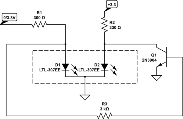
Aim is to use it as a power indicator, using a 3 legged bi-color LED (red=off, green=on), but I fail to see the feasability.

The red and green (separate) LEDS have already been switched and I understand the math to put the right resistors in. This much works! I'm lost when it comes to the bi-colour LED's common cathode.

Any suggestions? Common anode perhaps? Or PNP?


Rephrase:

In a model railroad I want to be able to choose between a traditional AC transformer (powersupply 1) or digital control (powersupply 2).

The switch (rotation) that I'm using for this has 2 separate channels:

  • one is used to power the rails,
  • the other could be used to indicate which powersupply was selected.


I plan to use either +3.3 or +5V DC (not decided yet) to drive bi-colour LEDS (to save space).

I want both leds to always be on (either red or green). A simpler solution to only power the "selected" led wouldn't properly visualise which powersupply was selected in a when in the dark. Basically, a LED should be red, unless selected (powered) by the switch (=green).


The original scheme worked for me when using separate LED's for red and green, but when I tied the cathodes together to simulate a bi-color LED, powering green did not switch off red. The new scheme works for me!

\$\endgroup\$
5
  • 6
    \$\begingroup\$ Schematic or it didn't happen. \$\endgroup\$
    – winny
    Commented Mar 12, 2018 at 14:36
  • 1
    \$\begingroup\$ You put current through an LED and it lights up. I'm not sure what you mean by "toggling" an LED. \$\endgroup\$
    – Finbarr
    Commented Mar 12, 2018 at 14:37
  • \$\begingroup\$ Well, we're lost too. Before telling us where you're stuck and the possible solutions you envision, you need to clearly explain what you have (LED datasheet, inputs, supplies available, schematics of what you tried...) and exactly what you want to achieve (outputs: which LED should be on, in which situation). \$\endgroup\$
    – dim
    Commented Mar 12, 2018 at 14:49
  • \$\begingroup\$ That circuit will not work with either common pin LEDs. What is your Vcc level? \$\endgroup\$
    – Trevor_G
    Commented Mar 12, 2018 at 14:49
  • \$\begingroup\$ Define source and output V and how will Red turn on if no power, so we assume there are two V sources?? Or is it two signals or just one that is complement of the other? \$\endgroup\$
    – D.A.S.
    Commented Mar 12, 2018 at 15:33

1 Answer 1

2
\$\begingroup\$

To use Jasser's circuit with CC R/G LED you can do this:

schematic

simulate this circuit – Schematic created using CircuitLab

\$\endgroup\$
0

Your Answer

By clicking “Post Your Answer”, you agree to our terms of service and acknowledge you have read our privacy policy.

Not the answer you're looking for? Browse other questions tagged or ask your own question.