I am trying to get a PWM signal with adjustable duty cycle using only analog components, hence using a timer is not possible. Now I got one way of using it, using the triangle waveform and putting it throw a comparator with the voltage supply, the result is a PWM signal. now I want another way of doing it
-
11\$\begingroup\$ using only analog components What if I told you that all digital components are basically analog components with only two (useful) states? Digital is just a simplification of analog. Basically digital components do not exist as the world is analog. \$\endgroup\$– BimpelrekkieCommented Mar 21, 2018 at 10:16
-
3\$\begingroup\$ and a PWM unit is, by @Bimpelrekkie's definition pretty much a digital device (the only thing necessary is that not only its values are discrete, but also the time steps are – and it's hard to argue that PWM doesn't fulfill that definition) \$\endgroup\$– Marcus MüllerCommented Mar 21, 2018 at 10:59
-
5\$\begingroup\$ and what do you mean by "using a timer is not possible"? Any oscillator is a kind of timer... So you definitely will need some kind of timer. \$\endgroup\$– CurdCommented Mar 21, 2018 at 11:17
-
2\$\begingroup\$ and BTW: what is the question? \$\endgroup\$– CurdCommented Mar 21, 2018 at 11:17
-
\$\begingroup\$ Thank you for your comments, @Bimpelrekkie you made your point clear but I am welling to use only "analog" components, so Curd I mean that I do not want to use a timer I know I will do a PWM signal but I want to implement it a different way. and my question is what are the ways of implementing a PWM circuit "using" only analog components \$\endgroup\$– user183026Commented Mar 21, 2018 at 11:42
4 Answers
You could, just for the fun of it, use an oscillator that makes low THD sine waves and then use an integrator to make your comparator compare with a value that gives the right duty cycle.
Here is one example of it:
Link to simulator.
- The left graph = the gate of the NMOS
- The second graph = the out = output of the top op-amp (comparator, PWM)
- The third graph = the output of the bottom op-amp (integrator)
- The fourth graph = the voltage across the rightmost capacitor
The fourth graph shows that the integrator correctly outputs a value that results in the correct duty cycle according to the input voltage.
The 10 kΩ resistor and the capacitor on the right is not part of the actual circuit, it is only there for the fourth graph.
You can make the 100 uH coil with a piece of copper wire and a pen. This coil together with the two capacitors will set the oscillating frequency, in other words the PWM frequency.
In the real world there's no ideal capacitors and inductors and mosfets, so you will probably want to make the two capacitors in the oscillator equal. This will increase the voltage at the gate of the oscillator. I am using 1 kΩ pull up and pull down on the oscillator, you might need lower like 100 Ω or larger. This greatly depends on the ESR of the capacitors and inductor.
Here is another flavor of the same circuit, the 1 nF capacitor in the link is not actual capacitors, they are the input and output capacitances of the mosfets. So all in all it's just 3 NMOS and 3 resistors, though you might want to use 10 kΩ or 100 kΩ in real life.
Or another flavor, you get the point.
Problems:
The integrator is a part of a typical PID, I am not using the P or D part as you can see. This means that if your input is going to vary fast, then you will get major overshoots and more or less an instable system. So this will work good if you are using a potentiometer with your fingers, but horrible if you are using it in some feedback loop without a P or D part.
It is important that the voltage at the gate of the mosfet is within the voltage range of the integrators output.
Make sure that the inductor is an air core inductor, just wire it yourself. If you use any metal core then too much energy in the oscillator will be lost due to eddy currents and the oscillator will halt.
What about using a 555 timer? If you google image search 555 PWM then you will get lots of schematics to make a circuit such as this.
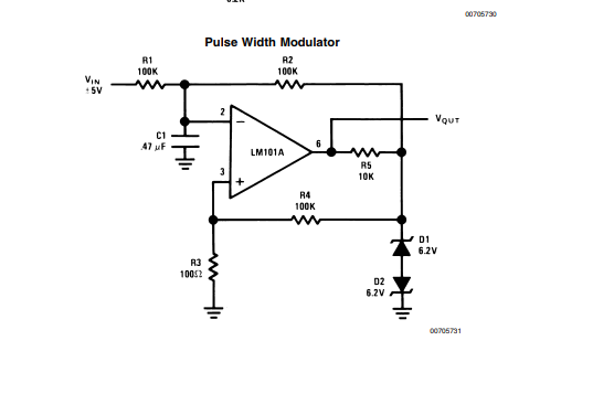
Also in the op amp application note by TI they give you an example of using an op-amp to give you a PWM signal:
Theres a few ideas!
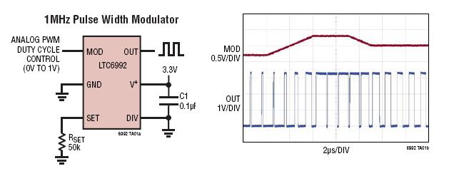
The LTC6992 falls into the category of an analogue component: -
- Pulse Width Modulation (PWM) Controlled by Simple 0V to 1V Analog Input
- Frequency Range: 3.81Hz to 1MHz
- 2.25V to 5.5V Single Supply Operation
-
1\$\begingroup\$ I've not seen that IC before. May have to get a few of those to use myself! +1 for this. Much simpler than my suggestions... And cheaper too! \$\endgroup\$– MCGCommented Mar 21, 2018 at 11:15
-
\$\begingroup\$ @MCG I've used it for controlling PWM on a rather bespoke 200 watt buck regulator and it worked just great. \$\endgroup\$– Andy akaCommented Mar 21, 2018 at 11:17
-
\$\begingroup\$ I've just got 10 on order to play around with! I have a few applications where this will save me a bit of time and money! \$\endgroup\$– MCGCommented Mar 21, 2018 at 11:20
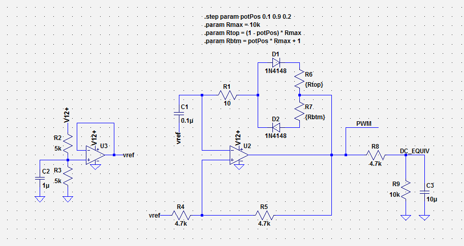
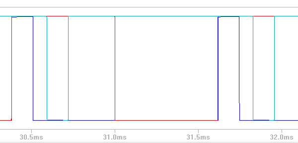
Here's one I've used. R6/R7 is a single pot; the junction between the two is the wiper. The PWM signal is available at the opamp output.
This circuit uses a virtual ground 'vref' as its oscillatory voltage center point, and you can adjust the cap, resistor, and pot values to set the frequency center point and range.
You don't necessarily need to buffer vref.


