2
\$\begingroup\$

I have an EEPROM (AT28C64B) multiplexed and connected to 3 seven segment displays,

I did so using a tutorial online from ben eater https://www.youtube.com/watch?v=dLh1n2dErzE&t=300s

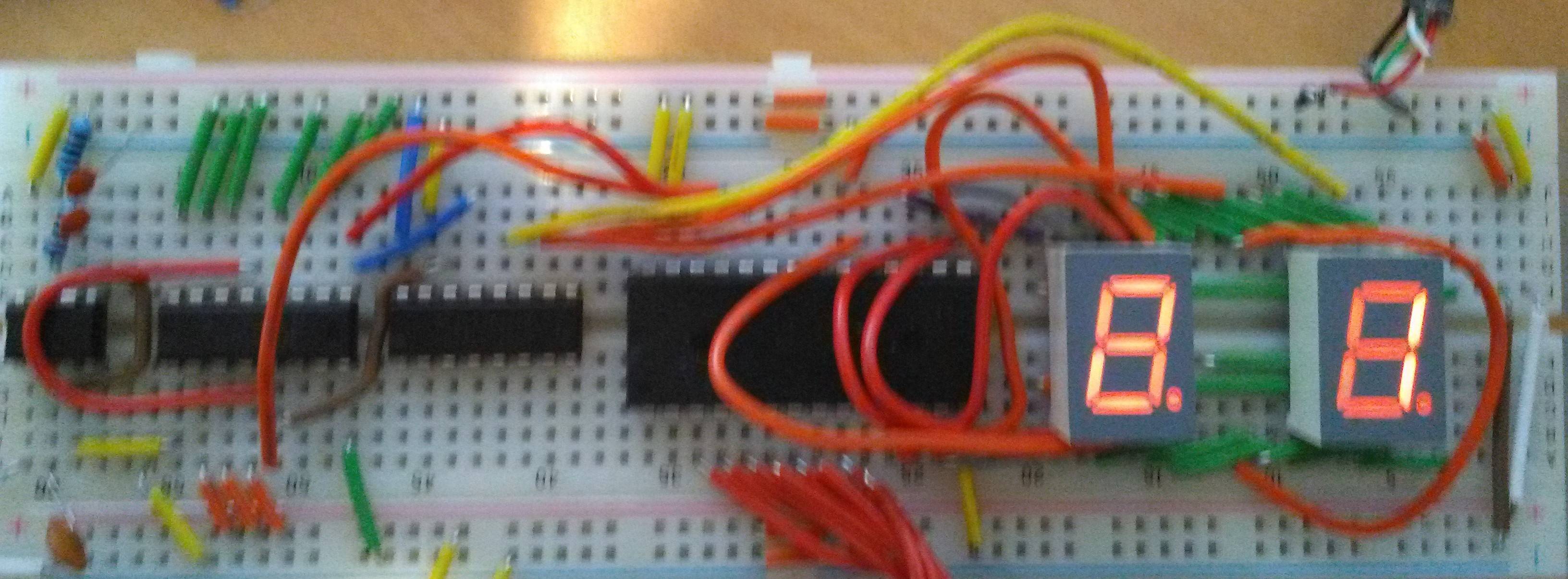
enter image description here

Sorry for the bad quality photo

Here's my setup, from left to right, the ICs I'm using, 555 timer connecting in Astable mode, SN74LS112 Dual JK flip flop, SN74LS139 Demultiplexer and the 7 segment display I'm using is called a SC05-11EWA (I only have two but a third is in the post)

I've had a problem with ghosting on the 7 segment displays and I'm not quite sure how to fix it, I have exhausted google, to no avail so I hope someone can help.

If you need further info feel free to comment.

Thanks, Patrick

(edit) enter image description here Here's a schematic I made using EasyEDA, sorry about the cluster it's my second time making a schematic.
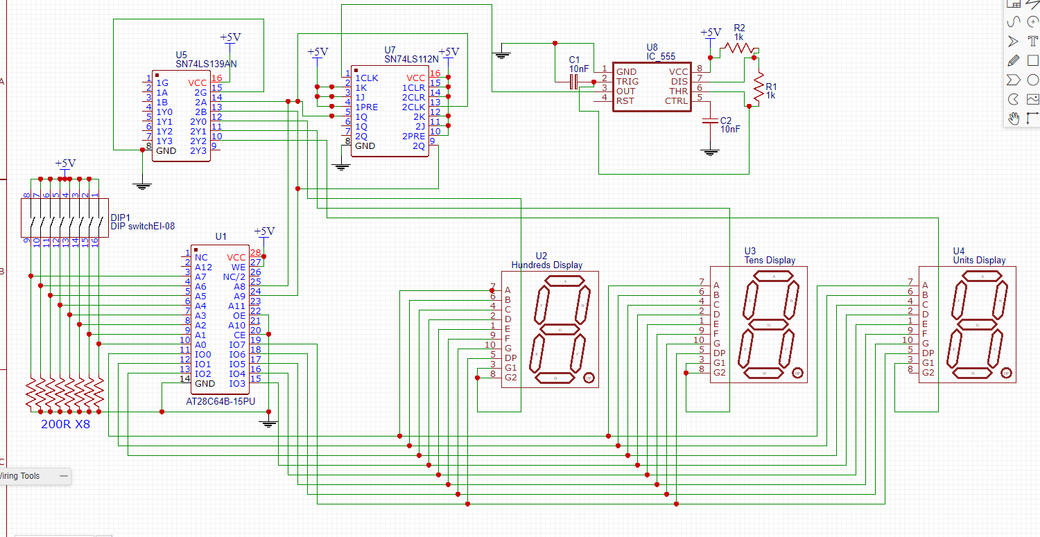
\$\endgroup\$
8
  • 1
    \$\begingroup\$ The ghosting is most likely happening due to the next value being shown on the previous display for one brief clock cycle. \$\endgroup\$ Commented Mar 28, 2018 at 14:20
  • \$\begingroup\$ I suspect @HarrySvensson is correct in that there is a race between the row and column drivers which leaves a brief time when LEDS are driven when you do not expect it. Proper sequencing is required for this type of circuit, but without a schematic it is impossible to confirm the root cause. \$\endgroup\$
    – Trevor_G
    Commented Mar 28, 2018 at 14:32
  • \$\begingroup\$ Without sounding like it's complaint after complaint, can you fix the schematic by moving nets under components to between components. It's hard to be certain of what's there with those nets. \$\endgroup\$
    – TonyM
    Commented Mar 28, 2018 at 15:15
  • 1
    \$\begingroup\$ Well, apart from trying to drive all seven segments from one 8mA TTL output with no current limiting resistors and no sign of decoupling capacitors anywhere... it all looks fine. \$\endgroup\$
    – Finbarr
    Commented Mar 28, 2018 at 15:58
  • 1
    \$\begingroup\$ Slow down your clock. 48 kHz is way overkill for this application, and the clock period is too short relative to the access time of the EEPROM. 500 Hz would be plenty. \$\endgroup\$
    – Dave Tweed
    Commented Mar 28, 2018 at 16:02

2 Answers 2

3
\$\begingroup\$

You have a race condition happening.

When the counter is changing the data presented from the EPROM will be indeterminate and as such LEDs will light at random for a short period.

As such you need to disable the drivers while the data is changing.

In this case you can use the clock signal from the 555 to control the output enable (OE, Pin 22) of the EEPROM such that it only drives the LEDs during the second half of the clock cycle.

Since you are using a negative edge triggered flip-flop for your counter, you need to invert the output from the 555 to feed that enable pin.

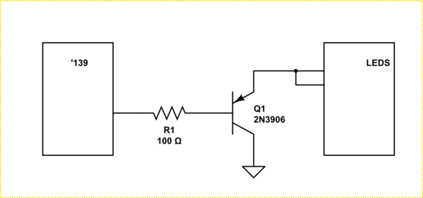
As others have mentioned, you also need some current limiting resistors in the LED lines. You are also asking a bit much of the 139 to power all segments, a transistor or MOSFET drive for the common would be prudent.

schematic

simulate this circuit – Schematic created using CircuitLab

\$\endgroup\$
4
  • \$\begingroup\$ Thanks for all your help, I have inverted the clock signal with a NOT gate & the output of that is connected to the JK flip flop and the chip enable pin, this has nearly fixed the problem. I understand what you're saying about the transistor but I don't know fully how to implement it. Would I connect the base of my 2n3904 to the base of the 139 and then connect the emitter to the cathode and the collector to 5v? \$\endgroup\$ Commented Mar 28, 2018 at 17:44
  • \$\begingroup\$ @PatrickMcCarthy only invert the signal to the rom enable..not the counter \$\endgroup\$
    – Trevor_G
    Commented Mar 28, 2018 at 17:49
  • \$\begingroup\$ @PatrickMcCarthy see update for a quick fix transistor drive. \$\endgroup\$
    – Trevor_G
    Commented Mar 28, 2018 at 17:57
  • \$\begingroup\$ Thanks very much I don't have any PNP transistors but I'll order some online \$\endgroup\$ Commented Mar 28, 2018 at 18:00
0
\$\begingroup\$

When the counter is changing the data presented from the EPROM will be the data of the previous display....

there is a very short transition period where a new display is selected and DATA of previous display are still activated.

\$\endgroup\$
3
  • \$\begingroup\$ The number displayed shouldn't change unless I change the value on the dip switches so I don't understand how that would cause my issue \$\endgroup\$ Commented Mar 28, 2018 at 16:42
  • \$\begingroup\$ @patrick-mccarthy: the DIP switch is only here to give the fixed part of the adress from A0 to A7, the 'real' adress is giving to A8 and A9 from 1Q and 2Q of the 74LS112 Dual J-K Flip-Flop... the adress presented to the EEPROM is in the form 00000000XX.... \$\endgroup\$
    – moyoumos
    Commented Mar 28, 2018 at 17:00
  • \$\begingroup\$ ...rather of the form FFFFFFFFXX with F=0 or 1 according to the coding of the DIP switch.... \$\endgroup\$
    – moyoumos
    Commented Mar 28, 2018 at 17:13

Your Answer

By clicking “Post Your Answer”, you agree to our terms of service and acknowledge you have read our privacy policy.

Not the answer you're looking for? Browse other questions tagged or ask your own question.