0
\$\begingroup\$

In the following amplifier circuit, voltage gain is required. Capacitors act as open circuit for DC analysis but short circuit for AC analysis (consider capacitor value to be very big). Find Voltage Gain Now MOSFET have 2 different equations for drain current, one for ohmic region one for saturation. How can one determine which equation to use here and for which transistor i.e. which one of the transistor is saturated and which one is not. (Early voltage Va = 50 Volts) Here is the problem I'm facing if I consider both transistors in saturation : Due to symmetry in gate circuit
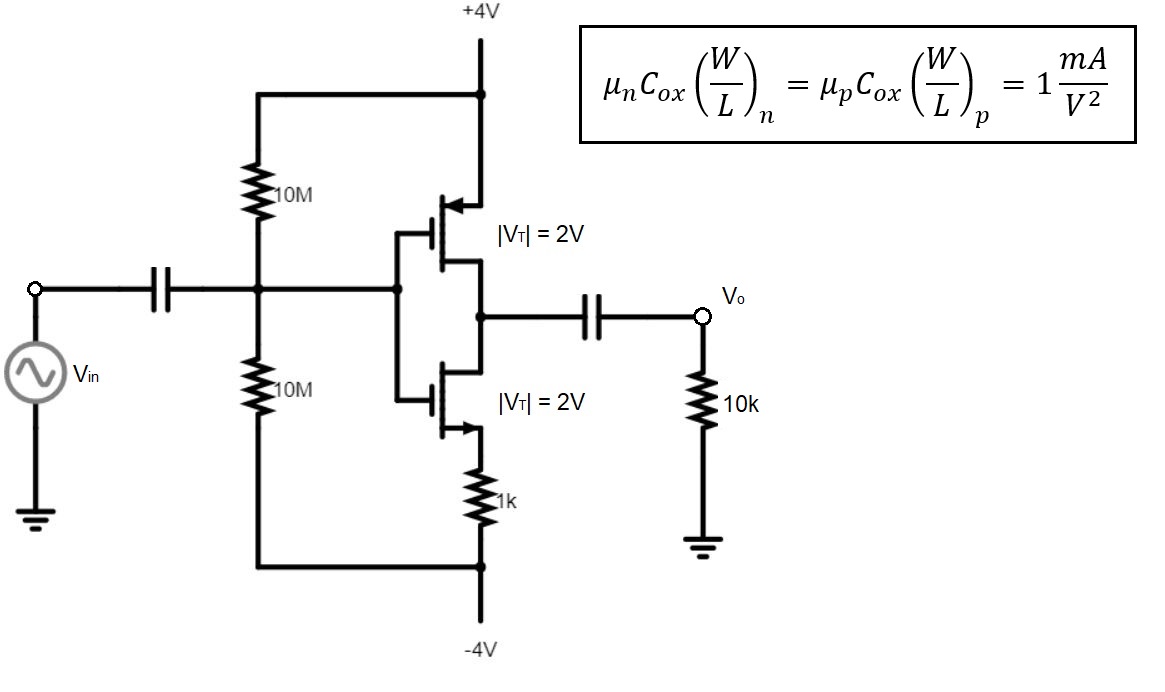
\$ V_{G} = 0 V\$

Now as for pMOS

\$I_D = \frac{k_p}2 (V_{GS}-V_T )^2\$

\$ = \frac{1}2 (-4 + 2 )^2 = 2 mA\$

Therefore voltage at the source of nMOS will be

VS = -4 + (1k-ohm x 2mA) = -2 Volts

So for nMOS VGS = VG - VS = 0 - (-2) = +2 V (= VT)

So overdrive voltage for nMOS is zero. This means no current should flow through it. But 2 mA drain current is from pMOS. That's why I'm confused weather both transistors are in saturation or one of them is in ohmic region?

\$\endgroup\$
2
  • \$\begingroup\$ Simply assume that bought MOSFET's are in a saturation region. And solve circuit \$\endgroup\$
    – G36
    Commented Mar 31, 2018 at 11:27
  • \$\begingroup\$ Very good, you know something. PMOS will work in triode region and NMOs in saturation. So please start by solving Id for NMOS in saturation. And use this result and solve for PMOS Vds. \$\endgroup\$
    – G36
    Commented Mar 31, 2018 at 17:50

2 Answers 2

0
\$\begingroup\$

At first, try to read this When an NMOS utilizes a PMOS current source load, which transistor is acting as the current source?

Now you need to check what current every MOS want to pass (forced) in a saturation region.

For PMOS:

$$I_{D2} = \frac{Kp}{2}(V_{GS} - V_T)^2 = 0.5m((-4V)-(-2V))^2 = 2mA $$

But the NMOS want to force

$$\frac{V_G - V_{GS}}{R_S} =\frac{Kp}{2}(V_{GS} - V_T)^2 $$

$$\frac{4V - V_{GS}}{1k\Omega} =0.5m(V_{GS} - 2)^2 $$

After you solve this you will get two solutions:

\$ Vgs =-1.236V\$ or \$ Vgs = 3.23607V\$

The first solution makes no sense, so \$ Vgs = 3.23607V\$ and \$I_{D1} = 0.763932mA \$

Hence \$I_{D1} < I_{D2}\$ we conclude that NMOS will work in saturation and PMOS in a triode region.

All that remains is to find \$V_{DS}\$ for a PMOS.

We can do this by solving this equation

$$0.763932mA = Kp(4V - 2V)V_{DS} - \frac{V_{DS}^2}{2}$$

And this time this solution is true \$V_{DS} = 0.427697V\$

Therefore the voltage at MOS's drain's is \$4V - 0.427697V = 3.57V\$

\$\endgroup\$
0
\$\begingroup\$

2 different equations for drain current, one for active region one for saturation.

You're mixing FET and Bipolar vocabulary, which is confusing. Bipolars have Saturation and Active region (and quasi-saturation in-between). Saturation occurs at low Vce, when the B-E diode passes high Ib.

For FETs the terms are the opposite:

  • "Saturation region" is the mode you use to build an amplifier, as is the case here. The term "active region" is much clearer, so that's what I'd use. The FET behaves as a voltage-controlled current source which is characterized by Id as a function of Vgs (and Vds), and transconductance is d(Id)/d(Vgs).

  • "Triode mode or linear region (also known as the ohmic mode)" occurs when the FET behaves like a resistor (hence "ohmic mode" is the most explicit).

If you want to build a common source amplifier (which is the case here) you need transconductance, which means using the active mode. Thus, do the calculatoins assuming active mode, then check that the FETs are indeed in active mode (saturation).

\$\endgroup\$
4
  • \$\begingroup\$ Oh yes. Thanks a lot. I was mixing the vocabulary. Instead of active region, I want to say ohmic region. So both the transistor will act in saturation (active) region. \$\endgroup\$
    – user175306
    Commented Mar 31, 2018 at 11:42
  • \$\begingroup\$ If we consider pMOS to be saturated then 2mA Drain current will flow. This will make Vgs for nMOS 2V. Now overdrive voltage for nMOS is zero. So it cannot conduct. Am I mistaken somewhere or what. Please provide solution if you can. \$\endgroup\$
    – user175306
    Commented Mar 31, 2018 at 14:23
  • \$\begingroup\$ Try putting your equations & calculations in the question. I think you have a sign error somewhere. Here, due to the cap at the output, drain current is the same for both FETs (except sign) ... \$\endgroup\$
    – bobflux
    Commented Mar 31, 2018 at 14:29
  • \$\begingroup\$ Sorry for delay. I've added my approach to find drain current in the edit. Please take a look at it. \$\endgroup\$
    – user175306
    Commented Mar 31, 2018 at 17:26

Your Answer

By clicking “Post Your Answer”, you agree to our terms of service and acknowledge you have read our privacy policy.

Not the answer you're looking for? Browse other questions tagged or ask your own question.