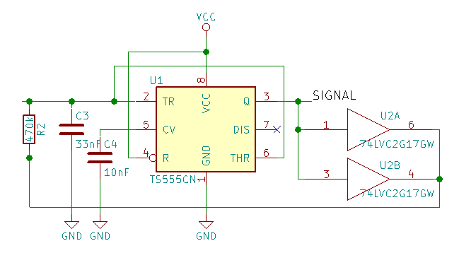
I'm trying to use a 555 timer to create a variable frequency from a resistance, the output frequency should be about 1 kHz up to 300 kHz. I'm using a TS555CN CMOS version, which can oscillate up to 2.7 MHz or so.
When using different values for R2, I see a linear relationship between the output frequency (measured using a scope) and 1/R2 for larger values of R1, but the frequency goes up less than expected for resistances below about 1k, and this effect gets progressively worse as the resistor values go lower, down to 10Ω where the frequency is just 1/3 of the expected frequency.
I've wired the 555 using the output as control, this as I need a 50% duty cycle. In earlier tests I noticed that, especially at lower resistor values, the duty cycle goes up more and more until it's about 70% and the output was far from a square block wave. This is of course an effect of the output not going to Vcc (3.3V for me), plus the internal resistance of the output. To solve this I put a non-inverting buffer on the output (U2 - actually two of them, as it's a dual package). That solved the duty cycle problem, and I'm getting perfect 50% square wave at all resistor values.
When trying the same with a ceramic cap instead of a film cap I got a less precise result (expected) but the linear part continued down to 470Ω, before the frequency really started to lag.
Changing the capacitor from 33 nF to 10 nF didn't make a change. The frequency itself of course changed, but the effect on linearity was the same, implying it has to do with the current. But here it ends... I don't understand why, as at 1k the peak charge current is no more than about 2 mA, while the buffers can supply some 20 mA each. Disconnecting one of the buffers did not make a difference.
(edit for additional info) The purpose of this circuit is to measure the resistance of a liquid - so the resistance is a given, and can not be changed. This will have to go down to about 50Ω...

