5
\$\begingroup\$

I have recently gotten back into electronics and have access to a lab with a signal generator and oscilloscope. I have been trying to teach myself how to use this equipment by building small and simple circuits.

Last night I wired a full-bridge rectifier on a breadboard. The diodes I used were EM518 diodes (those were the only ones that I could find in the lab). What I was trying to do was set up Channel 1 for the input (5VAC-RMS @ 60Hz). Then I wanted to set up Channel 2 to show the output ( ??VDC @ 120Hz). Below is a visual of how I set up the probes:

enter image description here

What I ended up with was a half-wave at the input and a half-wave of smaller magnitude at the output.

Why is this happening? Am I connecting the probe grounds the wrong way? After searching for how to properly connect ground leads, I am now more confused than I was before.

How is this done when working with circuits not connected to the mains? (I'll stay away from mains powered circuits till I understand what the hell I am doing).

Thanks!

\$\endgroup\$
8
  • 1
    \$\begingroup\$ Does your AC signal have a DC offset? \$\endgroup\$
    – Shamtam
    Commented Apr 10, 2018 at 17:40
  • 6
    \$\begingroup\$ Sig gen GND and scope GND are probably the same (definitely the same if you are probing both input and output with the scope), so you shorted D2 \$\endgroup\$ Commented Apr 10, 2018 at 17:41
  • \$\begingroup\$ DC offset was off when doing this. \$\endgroup\$
    – James85
    Commented Apr 10, 2018 at 17:46
  • 4
    \$\begingroup\$ "Ch1 Probe Gnd" == "Ch 2 Probe Gnd". They're internally connected in the 'scope, So you're shorting out your D2 in your bridge. \$\endgroup\$
    – brhans
    Commented Apr 10, 2018 at 18:18
  • 1
    \$\begingroup\$ You are confusing the scope. Connect one scope GND clip to Function Generator GND. The first GND will work as reference for the second scope probe. \$\endgroup\$ Commented Apr 10, 2018 at 19:13

3 Answers 3

5
\$\begingroup\$

schematic

simulate this circuit – Schematic created using CircuitLab

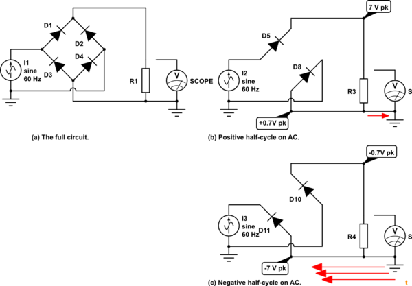
Figure 1. (a) The whole circuit. (b) What's conducting on positive half-cycles. (c) What's conducting on negative half-cycles.

You can't connect your scope probes to two different potentials. Fortunately your power supply had limited current drive so you don't appear to have damaged your equipment.

With a more powerful supply you could draw very large current (red arrows) and destroy the earth traces in your test equipment.

\$\endgroup\$
4
  • \$\begingroup\$ Or blow fuses... \$\endgroup\$ Commented Apr 10, 2018 at 17:54
  • \$\begingroup\$ That is why I am using low voltages on the signal generator. \$\endgroup\$
    – James85
    Commented Apr 10, 2018 at 18:07
  • \$\begingroup\$ @James85 - Low voltage is irrelevant. The short circuit will FORCE the voltage low. The question is, how much current will the supply provide? You might want to look up the specs on arc welders. \$\endgroup\$ Commented Apr 10, 2018 at 18:48
  • \$\begingroup\$ I think James is just saying that he is being cautious and learning with a safe, severely current limited signal generator before he moves onto bigger power. Smart guy. He'll live long and will save by not having to replace test equipment. \$\endgroup\$
    – Transistor
    Commented Apr 10, 2018 at 18:53
4
\$\begingroup\$

If this truly is your wiring:

enter image description here

you are shorting out your DC- rail via your scopeprobe. This will short the supply as well. The local DClink is +- about the return of the supply.

\$\endgroup\$
3
  • \$\begingroup\$ Sorry but I don't understand your explanation. If my probe grounds are separated, how am I shorting anything? \$\endgroup\$
    – James85
    Commented Apr 10, 2018 at 17:59
  • 6
    \$\begingroup\$ They are not separated. They are the same GND, actually, your home ground. You might want to see this: youtube.com/watch?v=xaELqAo4kkQ \$\endgroup\$ Commented Apr 10, 2018 at 18:01
  • \$\begingroup\$ Is there any way to avoid this situation and get the both input and output displays at the same time? \$\endgroup\$
    – Ghost
    Commented Sep 30, 2023 at 20:20
0
\$\begingroup\$

Firstly, you need to know: 1. How diode works 2. What happens to the diodes connected in a fullwave bridge rectifier configuration

To address 1, diode turns ON and conduct when the positive terminal of the diode reaches certain positive voltage (usually around 0.7V). This is known as forward bias. Any voltage below the 0.7V applied to the positive terminal will not turn ON the diode. If 0.7V or greater is applied to the negative terminal, it is considered reverse bias and diode will not turn ON as well.

Now that we have explained how diode works, let us look as the fullwave bridge configuration. When you connect a function generator with a sine wave as input to the fullwave bridge assuming that first half of the period, T, is positive and goes from 0V to peak of 5V. From 0V to 0.7V, your diode, D1, will not turn ON. D1 will only turn ON and conduct when voltage is between 0.7V to 5V. Diodes D3 and D4 will be in reverse bias and remain OFF at all times. Similarly, D2 will turn ON to complete the circuit.

Your problem comes in during the second half of the period, T. During this time, your sine wave voltage is negative with reference to GND. Positive terminal of D1 is at a lower potential than its negative terminal - hence reverse bias. D3 will not conduct as well since the voltage drop between both its terminals are close to 0V.

Based on the explanation above, this most likely results in half wave rectification.

http://www.circuitstoday.com/full-wave-bridge-rectifier

\$\endgroup\$
1
  • 2
    \$\begingroup\$ Welcome to EE.SE, Kenny. The OP (original poster) seemed to understand the operation of the bridge rectifier. I think that you've missed that the problem is that D2 is shorted out by scope and signal generator ground connections. That means that when the signal goes negative that D4 is connected forward biased across the signal thus creating a short-circuit. Tip: "Positive terminal of D1 is at a lower potential ..." Then it's the negative terminal. Use "anode" and "cathode" to avoid confusion. \$\endgroup\$
    – Transistor
    Commented Jul 9, 2019 at 6:39

Your Answer

By clicking “Post Your Answer”, you agree to our terms of service and acknowledge you have read our privacy policy.

Not the answer you're looking for? Browse other questions tagged or ask your own question.