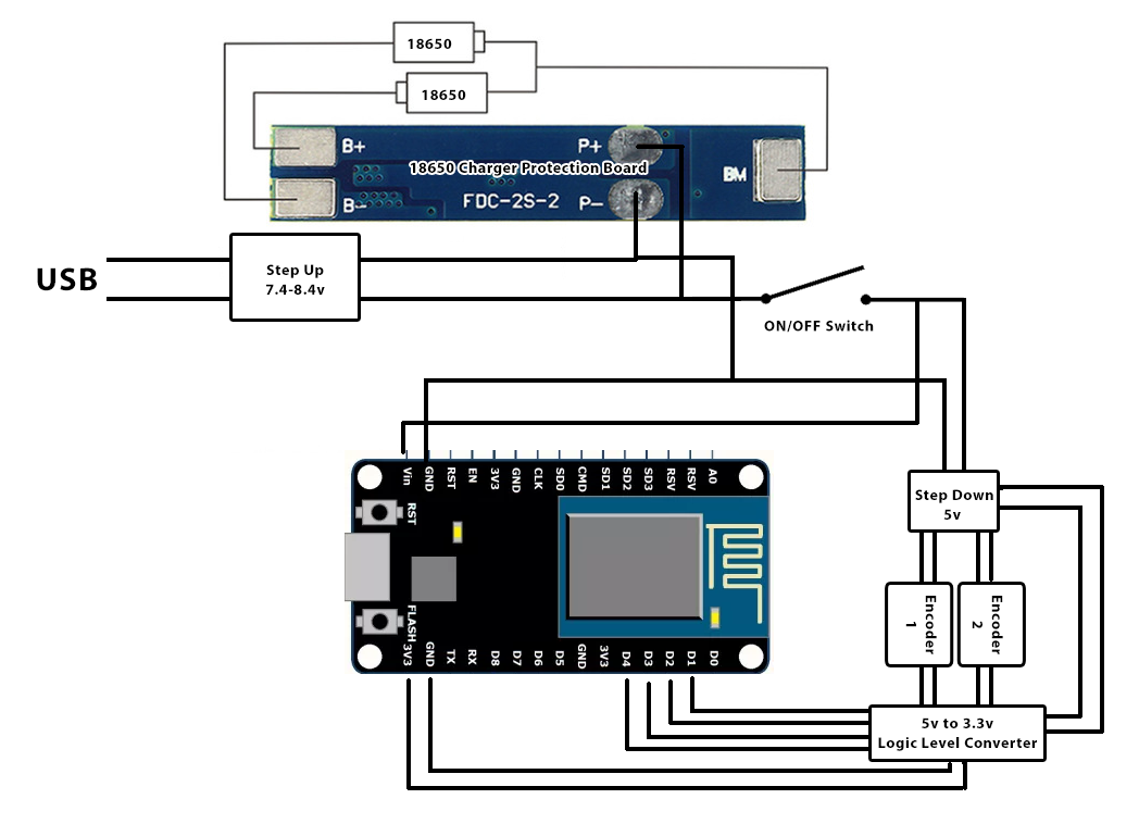
I am planning to use a NodeMCU with a couple of encoders to determine the position a telescope is pointing at. While running, the device will be connected to wifi all the time since it needs to interact with an app (or maybe on AP mode so a tablet/phone connects to it).
In the future I may also add a barometric pressure (BMP280) and temp/humidity (DHT11) sensors, gps, and a touch lcd. Probably wont have enough pins for this, but maybe using a MCP23017 could work. Anyway these are all just ideas, to start I will only use the 2 encoders. I haven't even received any of the devides yet, so in the meantime I'm reading and thinking of stuff I could do.
The device will have to be mobile since it may be used in places where there's no electricity, so I am thinking on powering it up with some 18650 batteries I have. I want it to work for about 4-6 hours before having to recharge it, and the device itself must have a charging (usb) port. I also need a 5v line since the encoders work with 5-24v (I choose to use the min 5v since it would be easier to use a logic level converter for input in the nodemcu). So I thought of doing something like this:
Pinout is not important right now, just the concept.
Would it even work? What will happen if I turn the switch on while the charging usb port is plugged in? Any simpler solutions? The charger protection board would be this one.

