0
\$\begingroup\$

I recently wanted to use a IRFZ44N N-Channel Mosfet (up to 50V) to control a 50 LED Panel with a current of 35V.

The Panel itself uses 230V AC which goes to a rectifier (?) which outputs 35V DC and powers the LEDs successfully.

I then cut the cable going to the negative terminal of the rectifier, connected the part coming from the LEDs to the Drain and the rectifier to Source.

Photo of the setup

Problems I have and things I found out:

  • When I power the lamp, I can't control the state of the LEDs (LEDs always on)
  • When I measure the power, all 3 Pins (Gate, Drain, Source) measure the full 35V (full output of the rectifier)
  • When I tested the Mosfet with 3v pins from my Raspberry Pi, it worked so I guess the Mosfet itself is not broken. Also tested 3 of the same Mosfets all with the same results
  • I added a 10kOhm resistor between the gate and the source. It didn't change anything and the LEDs stayed on
  • The Mosfet itself is rated for 50V so it sould be able to handle my 35V

I am obviously missing something, but what?

\$\endgroup\$
6
  • 1
    \$\begingroup\$ Seems that your PSU is in series with the FET. Pretty hard to tell how you connected it considering that it is a black blob... \$\endgroup\$
    – Wesley Lee
    Commented Apr 16, 2018 at 7:03
  • 2
    \$\begingroup\$ Post the schematic, please. (Nobody should be chasing the wires just to figure out what you are trying to do there.) \$\endgroup\$ Commented Apr 16, 2018 at 7:10
  • 1
    \$\begingroup\$ First you need to add a schematic, then you need to change your first sentence: 'with a current of 35V'. Did you mean voltage of 35V? Or current of 35A? \$\endgroup\$
    – MCG
    Commented Apr 16, 2018 at 7:40
  • \$\begingroup\$ I didn't do anything to the black blob, it came with the board. Will add some schematics \$\endgroup\$
    – Christian
    Commented Apr 16, 2018 at 9:41
  • 1
    \$\begingroup\$ Is that a metal box and is the black inlet mains power? If yes, then you have got yourself a deathtrap! \$\endgroup\$
    – winny
    Commented Apr 16, 2018 at 10:51

1 Answer 1

3
\$\begingroup\$

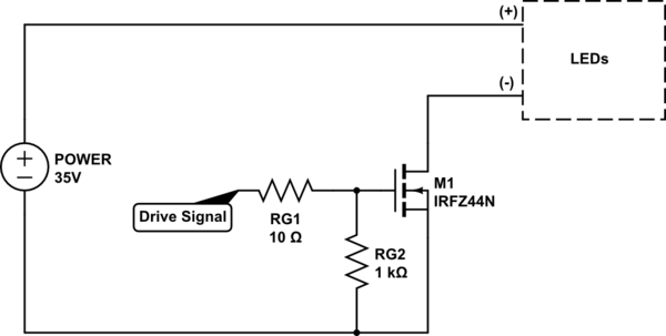
I could not understand how you connected the MOSFET and LED load. Here's how you should connect:

schematic

simulate this circuit – Schematic created using CircuitLab

Please note that Gate Drive signal should have a peak voltage of at least 10V for proper operation.

\$\endgroup\$
1
  • \$\begingroup\$ You're right the FET is upside down , with the drain to the negative wire. \$\endgroup\$
    – Dorian
    Commented Apr 16, 2018 at 21:38

Your Answer

By clicking “Post Your Answer”, you agree to our terms of service and acknowledge you have read our privacy policy.

Not the answer you're looking for? Browse other questions tagged or ask your own question.