2
\$\begingroup\$

Im now using Boylestad's book as a reference for making an RC Oscillator. it says in the book that for an RC Oscillator to Oscillate it needs

1) AV >= 29

2) that the phase shift of the RC network to amount 180 total.

the books says the formula F = 1/2pi(C)(R)(√N) will produce a 180 degree phase shift where N is the number of RC in the circuit

my target frequency is 4Mhz, and the available Capacitor is 100pF then 4Mhz = 1/2pi(100pF)(R)(√6) R = 162

Av for inverting amp is AV = Rf/R1

29V = Rf/162 Rf = 4698 Ohms

but the output im getting is like a noise and is random, and its super small in the femto volts region. at low frequency(60Hz ) this method works, but when i simply changed the values after doing the calculations provided by the book i can no longer make it work pls help

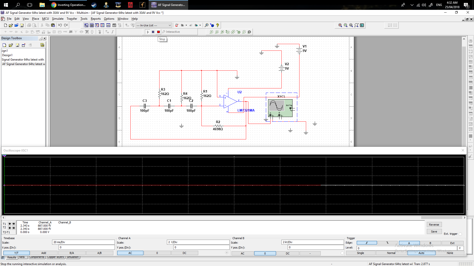
heres the output from my 4Mhz RC oscillator enter image description here

\$\endgroup\$
2
  • 2
    \$\begingroup\$ You can't 'just' change values. You have to look at the BW of your op-amp, output impedance, phase shift. Using that reasoning it should run at 10GHz. But you know that is not possible. \$\endgroup\$
    – Oldfart
    Commented Apr 24, 2018 at 21:07
  • 2
    \$\begingroup\$ Interesting. You play Fallout: New Vegas on the same computer that you do circuit simulation. I typically have two separate computers for gaming and work-related software.... Digressing. You mentioned that you found a textbook equation that will produce a phase shift. Which book are you referring to and what chapter contains that equation? Boylestad has written a lot of books. The circuit topology looks correct for a phase shifting oscillator, however. I ask what equations because I find multiple sources that provide the same relative equation but with different coefficients i.e. \$\sqrt{2N}\$ \$\endgroup\$
    – user103380
    Commented Apr 24, 2018 at 21:16

3 Answers 3

1
\$\begingroup\$

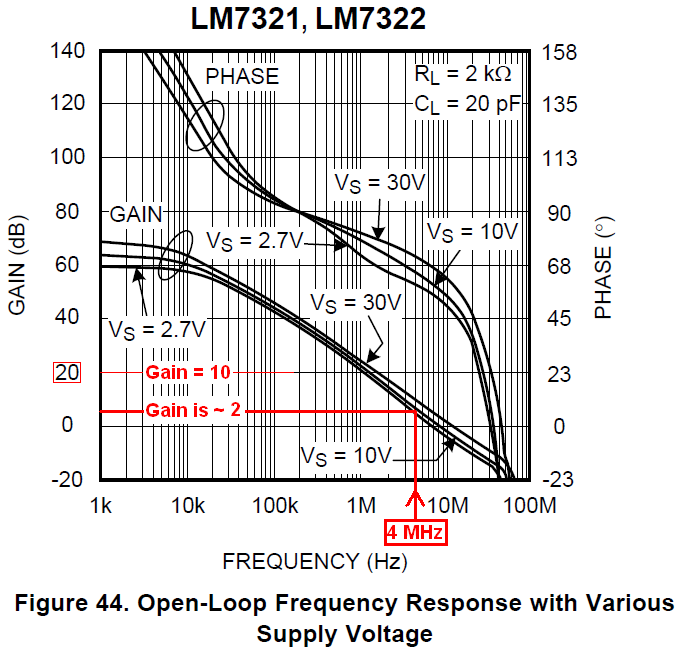
There are other things wrong with the design, but here is a very simple analysis. The LM7321 has a Gain-Bandwidth Product (GBW) of 20 MHz. Your circuit has a primary frequency of 4 MHz. At that frequency, the opamp has a gain of 5 and you need a gain of 29. The opamp will not work in this application.

\$\endgroup\$
1
\$\begingroup\$

The circuit diagram contains a severe error!

Look at R1 - it is placed directly across the opamp input terminals! Hence, it cannot fulfill the desired function as part of the feedback network. Instead, it must be located between C2 and the inverting input of the opamp.

\$\endgroup\$
1
  • \$\begingroup\$ I suspect R2 was copypasted from a transistor RC oscillator circuit. It would be part of the bias network. \$\endgroup\$ Commented Dec 3, 2019 at 20:21
0
\$\begingroup\$

How can you expect to get your op-amp to be able to produce a gain of 29 at 4 MHz. Read the data sheet and understand the open-loop gain. The open-loop gain is the best any op-amp can muster: -

enter image description here

\$\endgroup\$

Your Answer

By clicking “Post Your Answer”, you agree to our terms of service and acknowledge you have read our privacy policy.

Not the answer you're looking for? Browse other questions tagged or ask your own question.