0
\$\begingroup\$

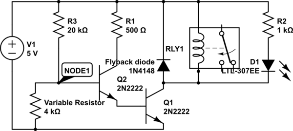
I'm building a circuit that can turn on a relay when the variable resistor cools down.

Its operating principle is cooling down the variable resistor increases its resistance, causing the voltage at Node 1 to increase until BJT 2 turns on, driving BJT 1, driving the relay. The LED is there as a visual indicator.
schematic

simulate this circuit – Schematic created using CircuitLab

However, when I built, I observed some strange behavior: upon cooling the variable resistor, after about 2 seconds the LED begins to glow and over the next second increases in brightness. Then, when the relay turns on, instead of a single "click", over the next second I hear a buzzing sound as the relay oscillates on and off before staying turned on.

When turning off (letting the variable resistor warm up), first the LED begins to grow dim, and then the relay, instead of cleanly turning off, oscillates for a second before remaining open. Moreover, when the relay is bouncing, the LED grows very slightly brighter (I don't think this is just my imagination).

My current understanding of the circuit is that as the resistance of the Variable Resistor increases, the current is amplified by the two transistors and gradually increases the current flowing through the relay until it turns on. While I know that relays can experience contact bounce, especially when run at less than rated voltage, I have no idea why it should oscillate for so long, or why the LED should grow brighter.

What circuit effect is responsible for the relay bouncing for so long?

EDIT: I'm not looking for how to fix my problem - I did that simply by making the relay a latching relay. What I want to know is the why - the reason it was bouncing for so long.

EDIT 2: The relay is driven by a 5V switching step-down regulator that draws power from a 8.4V battery. It turns on a 30W heating coil (driven by the same battery).

\$\endgroup\$
6
  • \$\begingroup\$ I dont know about the oscilation. But as for your LED glowing brighter, while the relay is bouncing - it is likley acting as a Marx generator. The relay connectors act as capacitors while they are apart. When you move charged capacitor plates away from each other, they generator voltage - which is how a Marx generator works. (From memory its a Marx generator) \$\endgroup\$
    – user160063
    Commented Apr 25, 2018 at 0:40
  • \$\begingroup\$ No! Its called a Wimshurst machine. \$\endgroup\$
    – user160063
    Commented Apr 25, 2018 at 0:47
  • 3
    \$\begingroup\$ Where is your bypass capacitor of 470 uF or so to stabilize the power rail? \$\endgroup\$
    – user105652
    Commented Apr 25, 2018 at 1:05
  • 1
    \$\begingroup\$ Imagine if the transistor just barely turns on and then the supply voltage drops. Now, consider what happens to the supply voltage when it suddenly has to engage the relay. \$\endgroup\$ Commented Apr 25, 2018 at 1:06
  • 2
    \$\begingroup\$ You need to add some hysteresis so that once Q2 starts to turn on, Node 1 voltage has to drop significantly before Q2 turns off. \$\endgroup\$ Commented Apr 25, 2018 at 1:14

1 Answer 1

3
\$\begingroup\$

This kind of oscillation is called "chattering".

To avoid this you should add bypassing across the 5V line to ground (maybe 1uF ceramic in parallel with 100uF electrolytic).

Add a 100nF across the variable resistor.

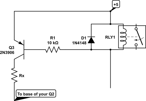
And add some hysteresis. That is a bit difficult to do with your present circuit, one way is to add a PNP transistor as follows:

schematic

simulate this circuit – Schematic created using CircuitLab

Pick Rx to add a bit of hysteresis compatible with your desired switching points.

You may wish to try this without the 100nF or add a series resistor to the base of perhaps 5-10K and retain the cap across the variable resistor, to keep from slowing the positive feedback. Basically you want the hysteresis to take effect immediately and the changes from the variable resistor to be slowed a bit.

\$\endgroup\$
4
  • \$\begingroup\$ So, if I understand you rightly, what is happening is that when the relay switches, the voltage on the 5V rail falls, causing the relay to turn off, causing the cycle to repeat itself. However, what is causing the voltage to drop? The current through the relay is being slowly increased by the transistor setup (as evidenced by the LED), so what causes a current draw spike when the relay switches? \$\endgroup\$
    – dpdt
    Commented Apr 25, 2018 at 16:15
  • \$\begingroup\$ It could be the lack of bypassing on the supply, it could be the inductance in your layout, it could be EMI from the contacts (if they are actually switching something). Lots of possibilities. The fact is, in your original circuit, your noise immunity is zero at the switching point so any deficiencies will have an effect. \$\endgroup\$ Commented Apr 25, 2018 at 17:13
  • 1
    \$\begingroup\$ @SpehroPefhany MAN, you are a genius! I have the same problem and had been facing me for days now, I tried the capacitor solution and it worked like a charm. Guys like you must be honored! \$\endgroup\$ Commented Jun 17 at 20:50
  • \$\begingroup\$ @SpehroPefhany, forget to ask. Can you please explain the science behind it, why did it the 100nf capacitor stopped the chattering effect? \$\endgroup\$ Commented Jun 18 at 21:40

Your Answer

By clicking “Post Your Answer”, you agree to our terms of service and acknowledge you have read our privacy policy.

Not the answer you're looking for? Browse other questions tagged or ask your own question.