0
\$\begingroup\$

I have been trying a lot to get my circuit work. I want the led to light up when the LDR receives no light and vice versa. I have found that the LDR offers the resistance of approximately 6k ohms when light is exposed on it and 66k ohms when light is not exposed to it. So I have used the resistors with those value. But I am not being able to achieve it enter image description herein the simulator. Also there is glowing of the led in which lesser current is flowing but there is no glowing when more current is flowing. Please point out my mistakes and suggest me to get my circuit work. I want the current to flow through the transistor "only" when there is light exposed to the LDR (possibly by keeping the low resistance for this path compared to the closed path of the LED). And when there is darkness, the current should not flow through the transistor leaving only a single path for the current to pass i.e. through the LED. Thanks for the help.
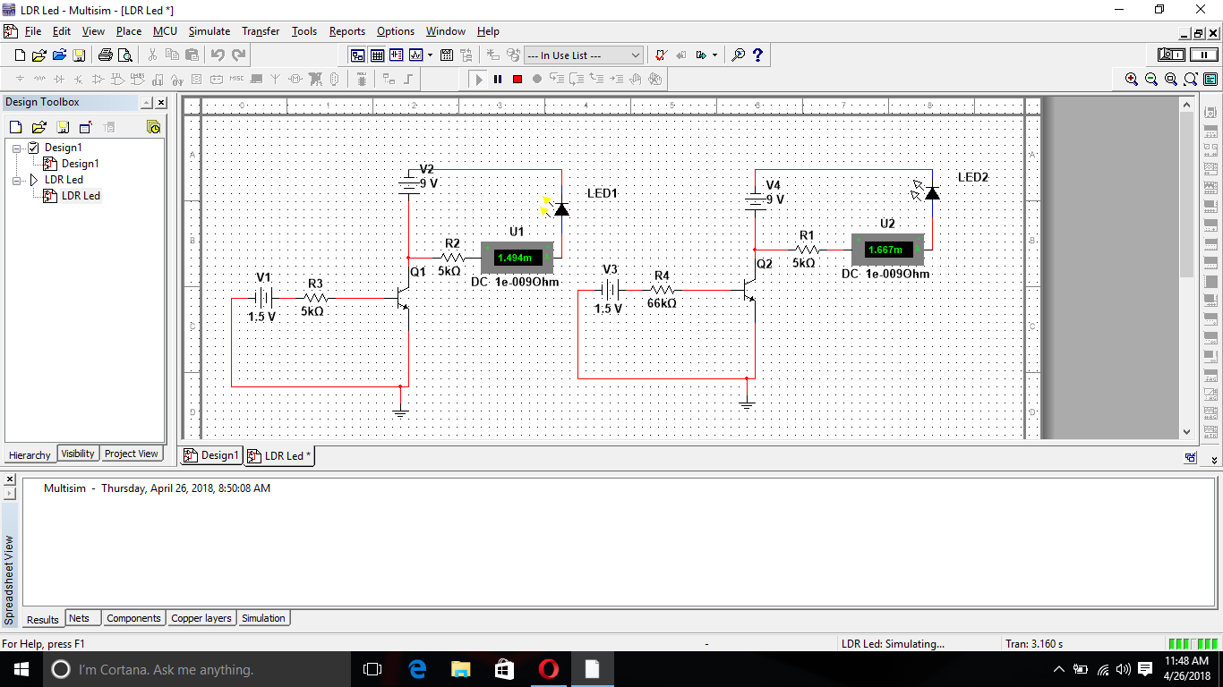
edit: The source in the collector circuit needs a ground return. Why is it so?

\$\endgroup\$
5
  • \$\begingroup\$ You should probably use an opamp in a comparator configuration and feed the output of that into the transistor that should be configured as a switch \$\endgroup\$
    – SRR
    Commented Apr 26, 2018 at 6:58
  • \$\begingroup\$ would you please explain further?\ \$\endgroup\$
    – G-aura-V
    Commented Apr 26, 2018 at 7:10
  • \$\begingroup\$ The base-emitter circuit and collector circuit are totally independent. \$\endgroup\$
    – Chu
    Commented Apr 26, 2018 at 7:12
  • \$\begingroup\$ but there is a role of base voltage for letting the current through the transistor. Isn't it @Chu? \$\endgroup\$
    – G-aura-V
    Commented Apr 26, 2018 at 7:18
  • \$\begingroup\$ The source in the collector circuit needs a ground return. \$\endgroup\$
    – Chu
    Commented Apr 26, 2018 at 7:21

1 Answer 1

1
\$\begingroup\$

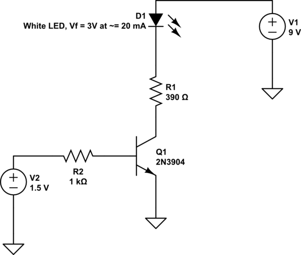
You should not disconnect your powersupply's ground connection with the transistor. The way you draw it the LED is connected to a closed loop that is not really affected by the state of the transistor. So schematic wise you're probably looking for something like this.

Component values give roughly 15 mA LED current.

Idrive ~= (V2 - Vbe_Q1)/R1 ~= (1.5-0.6)/1000 = 0.9 mA.
I_LED ~= (V1 - V_D1)/R1 = (9-3)/390 = 15 mA.
Use lower value of R1 for more current.

schematic

\$\endgroup\$
8
  • \$\begingroup\$ The downvoter does not understand how to vote properly. If downvoting an answer like this one, which addresses the main fault with the original circuit, a downvoter MUST say why - as otherwise they make it seem like the answer is fundamentally wrong - which is not the case. Downvoting in this manner is about equivalent to trolling. \$\endgroup\$
    – Russell McMahon
    Commented Apr 26, 2018 at 8:06
  • \$\begingroup\$ I'm neither an upvoter nor a downvoter, but looking at the edit history it looks like the original schematic didn't make much sense unless you read the fine-print. The right way to show that the values doesn't mean anything is to leave them out, not just write anything random and hope that people won't try to build it. \$\endgroup\$
    – pipe
    Commented Apr 26, 2018 at 8:33
  • \$\begingroup\$ As per my understanding, the current doesnt flow until the circuit is closed. For closing the circuit, the base voltage must exceed the breakdown voltage (0.7V). Here, the LDR(5k & 66k resistor in the schematic) is used to limit the voltage. When the LDR offers 5k resistance, base voltage exceeds the breakdown voltage due to which the current flows through the transistor (less resistive path). But when the resistance offered by LDR is 66k, the current cant flow through the transistor which leaves only the path through the LED to complete the circuit.Is anything wrong with my understanding? \$\endgroup\$
    – G-aura-V
    Commented Apr 26, 2018 at 9:08
  • \$\begingroup\$ Not exactly... you have a diode in the base emitter path of your transistor which has a forward voltage of 0.7V - so it's not the breakdown voltage. What your LDR does is controlling the current going into the base ((1.5V-0.7V)/RLDR) which is then amplified by factor B... so IC = B * IB. So there will always be some current (probably negligable with high base resistor) trough the transistor. \$\endgroup\$
    – po.pe
    Commented Apr 26, 2018 at 9:16
  • \$\begingroup\$ Thats the thing I was missing. So if I keep the source voltage below 0.7, there will be no any current through the transistor and I can get my led lit up. Right? Wait, doesnt the LDR function as the voltage divider like the resistor does? \$\endgroup\$
    – G-aura-V
    Commented Apr 26, 2018 at 9:27

Your Answer

By clicking “Post Your Answer”, you agree to our terms of service and acknowledge you have read our privacy policy.

Not the answer you're looking for? Browse other questions tagged or ask your own question.