2
\$\begingroup\$

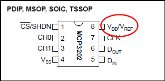
I'm trying to work out whether I can talk via SPI without level conversion between a PIC at 5V and an MCP3202 ADC at 4.096V (Vref and Vdd share a pin on the ADC).
enter image description here

I looked at the data sheet for the ADC and found the following:
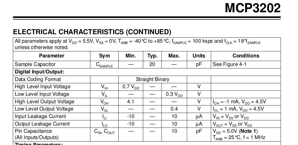
Digital specs for MCP3202

I'm a bit confused by the "Low Level Input Voltage" line, for example. You see, normally I'd interpret the 0.3Vdd in the Max. column as saying "Every chip has a low level input of at most 0.3Vdd". But that doesn't help me - I want to know (for example) that my PIC's low-level output (guaranteed <=0.6V) is less than the low-level input.

Now, I presume that I'm reading things backwards, and the "Low level input voltage" line means "As long as the voltage is below 0.3Vdd, the MCP3202 will regard it as a digital zero". After all, that's the only useful spec I could imagine. However, this is backwards from what Max. and Min. for other specs tends to mean (for example, the Input Leakage Current is guaranteed to be less than 10µA, not at least 10µA!)

Have I understood this correctly?

\$\endgroup\$
3
  • \$\begingroup\$ Here's quite a good link on typical logic levels for various logic families. \$\endgroup\$
    – Oli Glaser
    Commented Aug 4, 2012 at 18:16
  • \$\begingroup\$ @Oli - this one too. \$\endgroup\$
    – stevenvh
    Commented Aug 4, 2012 at 18:33
  • \$\begingroup\$ Thank you both. My question was really about how to interpret the data sheet, but these look helpful as well - especially as the PIC seems to allow different logic types on its input pins. \$\endgroup\$ Commented Aug 4, 2012 at 19:15

1 Answer 1

5
\$\begingroup\$

(edit: misunderstood a sentence in the question; I thought that you had connected Vref to the Vdd pin. I added a picture of the pinout to the question.)

Yes, it's confusing when it means that the maximum is minimum xxx :-)

"As long as the voltage is below 0.3Vdd, the MCP3202 will regard it as a digital zero"

That's the right interpretation.

But it's not a good idea to use the same voltage for power and ADC reference. Your power supply voltage isn't clean enough. Power should be a bit higher (what's wrong with 5 V?), and you use a voltage reference for the ADC reference voltage (maybe that's what the 4.096 V is?), or you use an RC filter to derive the reference from the 5 V if the absolute accuracy isn't important.

The problem is not in the maximum low, and minimum high levels, but in the maximum high. The PIC will output 5 V, which is a volt higher than the ADC's supply. Absolute maximum ratings, on page 2 of the datasheet say that no voltage should exceed Vcc by more than 0.6 V. Absolute Maximum Ratings. Read below the table:

*Notice: Stresses above those listed under “Maximum Ratings” may cause permanent damage to the device. This is a stress rating only and functional operation of the device at those or any other conditions above those indicated in the operational listings of this specification is not implied. Exposure to maximum rating conditions for extended periods may affect device reliability.

(my emphasis)

So, if you would use for instance the MCP1541 as a reference you can use a 5 V supply for that, and the ADC.

\$\endgroup\$
5
  • \$\begingroup\$ Using power as reference is useful for ratiometric applications such as a bridge. Doing this makes the reference 100.0000% correct (assuming you can deal with any noise). \$\endgroup\$
    – Russell McMahon
    Commented Aug 4, 2012 at 18:07
  • \$\begingroup\$ @Russell - well, I would use the 4.096 V reference for the bridge :-) \$\endgroup\$
    – stevenvh
    Commented Aug 4, 2012 at 18:09
  • \$\begingroup\$ Ah, I obviously wasn't clear. There's a 5V regulator powering both the PIC and a 4.096V reference, which is also the supply for the ADC (since that's how the chip is designed). \$\endgroup\$ Commented Aug 4, 2012 at 19:12
  • \$\begingroup\$ Anyway, thank you very much for the help - I'm going to use a Zener clamp for the output from the PIC (and hence input to the ADC). The other bits should be fine, I think. \$\endgroup\$ Commented Aug 4, 2012 at 19:13
  • \$\begingroup\$ @Rupert - Yes, now that I had a look at the datasheet I see that Vcc and Vref share the same pin. It would have helped if you put a link to the datasheet in the question. (I'll do it right away.) Don't forget resistors for the zeners (you'll need 3 of them: Din, CLK, CS). \$\endgroup\$
    – stevenvh
    Commented Aug 4, 2012 at 21:03

Your Answer

By clicking “Post Your Answer”, you agree to our terms of service and acknowledge you have read our privacy policy.

Not the answer you're looking for? Browse other questions tagged or ask your own question.