16
\$\begingroup\$

Short version: How do I make an analog multiplier that takes two analog DC inputs?

Long version:


I made a comment recommending Ben Eaters videos for another question, while doing so I ended up watching some myself (again) and thinking to myself "hmmm... I wonder if it would be easier to make some parts purely analog".

The bus could be just one wire where different voltage levels would later be translated to bits with an ADC.

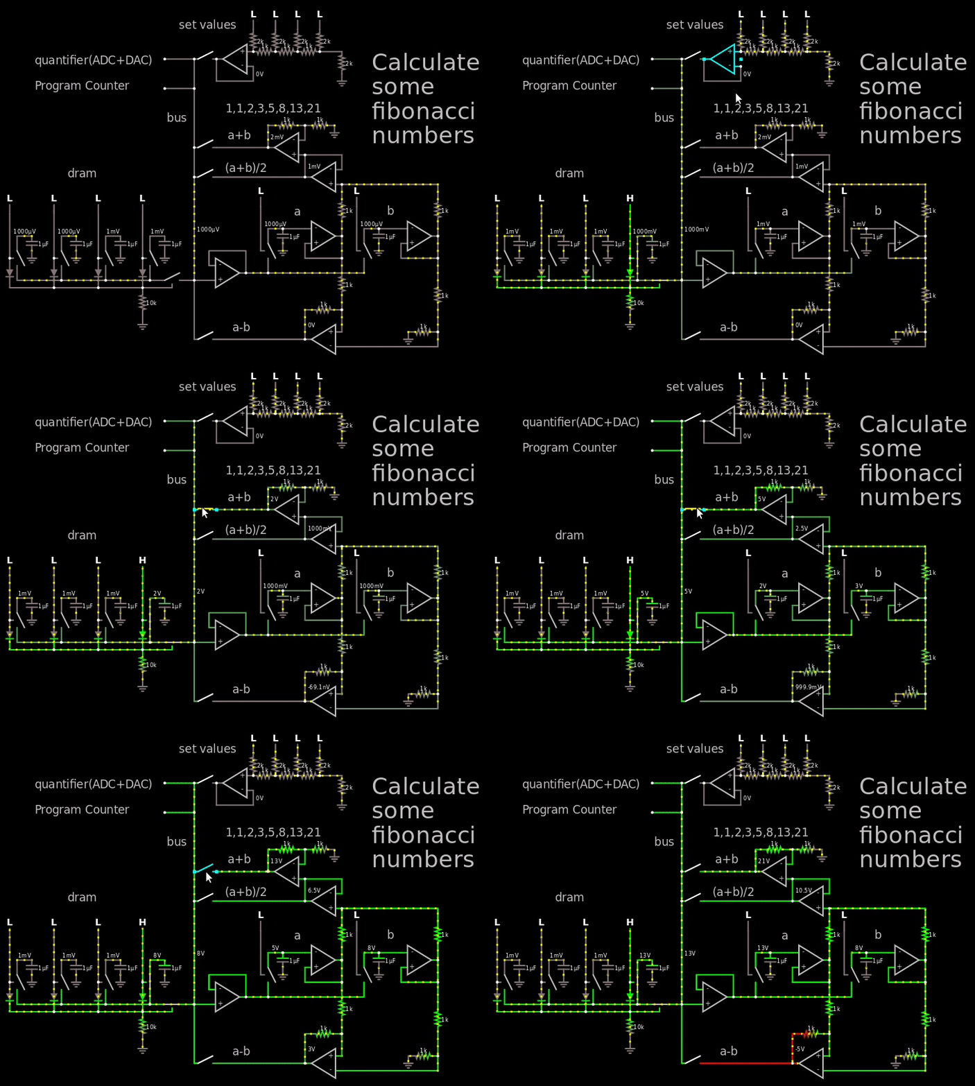
Just messing around a bit I came this far which theoretically can calculate the Fibonacci numbers:
enter image description here
Figure 1, small demo of hybrid computer calculating the first fibonacci numbers

Link to simulator.

In the gif above I go way out of the voltage range so it's easy to see the fibonacci numbers, in reality I would just use the 250 mV = binary 1 (the LSB at the "set values") and then let it propagate through the DRAM which holds 4 bits per capacitor.

The important part to look at in the gif is the output of the op-amp to the right of the "a+b" text, it shows the Fibonacci numbers.

In between every operation I would quantify the answer by using an ADC followed by a DAC. So if I would read 1.1V then the DAC would turn it into a 1.0 V which afterwards would be stored in the DRAM. And then once every X clock the entire DRAM would have to go through the quantizer to make sure the capacitor doesn't float away.

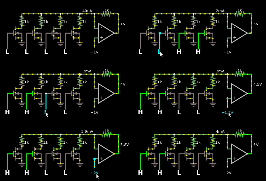
The ALU is only able to do +, - and average. I was thinking about making the multiplication and came to a halt. I've made and seen diode based multipliers before, but I don't want to use them because the diodes has to be matched. I rather use resistors that I can trim with a potentiometer. Anywhoo, I came up with a hybrid multiplier, half analog, half digital.

So I made a first with identical resistors everywhere.
enter image description here
Figure 2, naive multiplier between digital numbers and analog values. The digital value is offset by 1.

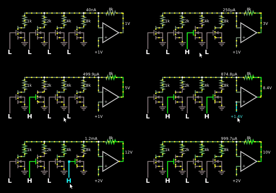
Which I then turned into this with binary weights:
enter image description here
Figure 3, naive multiplier between binary weighted digital numbers and analog values. The digital value is offset by 1.

This reminded me of R2/R ladders, but I couldn't make them work with the op-amp.

However, I thought about how R2/R ladders worked, and I remembered that their output is multiplied by their voltage source. So I finally came up with this design:

enter image description here
Figure 4, R2/R based multiplier between binary weighted digital numbers and analog values

I do like it, the only problem however is that the bus is analog, just one wire. So if I'm forced to use the solution in figure 4 above, then I'm forced to use another ADC at the multiplication area of the hybrid CPU. I can't reuse the one at the quantizer area.

Time for the question:

How should I make a multiplier that takes two analog inputs?

  • I do not want the solution that is based on 3 diodes that and 4 op-amps because you can't trim diodes. My belief is that if they are mismatched then they will give an answer that is off by more than 250 mV. I have not tried this in the real world.
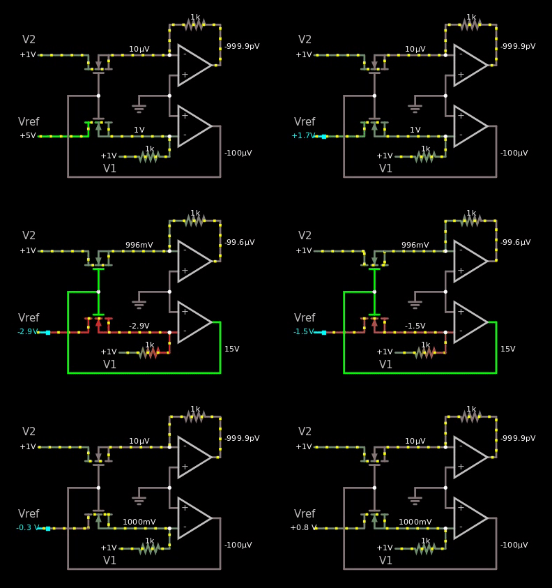
  • I have tried the MOS based multiplier in the link literally an inch above this word, but I don't know if I'm dumb. I can't get it to work in the simulator. See gif below for failure of MOS implementation. Or click this link for the simulation.
  • I do not want to throw a microcontroller at the problem.
  • I do not want to use a motor that rotates and uses some shenanigans.
  • I was thinking about using a RC filter in a lowpass formation to get hold of the \$e^{\frac{-t}{RC}}\$, charge and discharge and use a ramp + measure the time it takes for the capacitor to reach some value. It's the same idea as with the diode, it's just much much slower, not that I really care. Though I can use a resistor to trim the RC constant. I would prefer not using this solution because it feels... like I'm solving it in the wrong way.
  • The precision doesn't have to be perfect, right now it's just 4 bits per capacitor, this gives each level \$\frac{4}{2^4}=0.25\$ V if VDD is 4 V. Though in the future, it would be fun to store 8 bits per capacitor.
  • After the multiplication has been done, it will be taken to the quantizer to make sure the value is as close to a binary value as possible. So small errors are okay.

Here's the gif that shows my failure trying to make the MOS based one:
enter image description here
Figure 5, I copied the schematic from the wiki link above, yet it doesn't work in the simulator.

If it would have worked, then I should have seen the value 1 V somewhere as I changed the voltage of the reference from 5 V to -5 V.

\$\endgroup\$
3
  • 1
    \$\begingroup\$ The first time I saw an analogue multiplier, it was using a set of long tails: analoglib.net/wordpress/wp-content/uploads/2013/10/image5.png \$\endgroup\$
    – Oldfart
    Commented May 10, 2018 at 9:51
  • 2
    \$\begingroup\$ does the gilbert cell work down to DC? I reckon it is used to mix RF \$\endgroup\$ Commented May 10, 2018 at 10:00
  • 1
    \$\begingroup\$ @VladimirCravero A gilbert cell is in essence a multiplier - think about it, if you multiply two signals, one at f1 and one at f2, you get an output at f1-f2 and f1+f2, which is what a mixer does. They are also used for variable gain amplifiers for this reason - one signal will be a constant (the gain setting) the second will be the thing you want to amplify. \$\endgroup\$
    – Joren Vaes
    Commented May 10, 2018 at 10:28

5 Answers 5

11
\$\begingroup\$

If you want to build an analogue multiplier that is a little off-the-beaten track then consider what happens when you feed an analogue signal through an analogue switch but control the analogue switch with PWM at a high frequency (significantly above nyquist to make life easier).

If the PWM is 50% mark-space then the baseband analogue signal is attenuated by half. Clearly you need to use a recovery filter to remove switching artefacts. But with this technique you can amplitude modulate an analogue signal by varying the PWM duty cycle: -

enter image description here

You can also make it into a 4 quadrant multiplier. One analogue input controls a pulse width modulator. The other analogue input is switched.

Just a thought in case you are interested.

More details here

\$\endgroup\$
3
  • \$\begingroup\$ This is a very interesting approach! \$\endgroup\$
    – Joren Vaes
    Commented May 10, 2018 at 19:57
  • 1
    \$\begingroup\$ Hmm, using PWM where the amplitude is one voltage, and the duty cycle is the other relative voltage, and then LP filtered. That's actually not a bad idea. \$\endgroup\$ Commented May 10, 2018 at 21:10
  • 1
    \$\begingroup\$ It is used in some radios as modulators and in LVDTs as position demodulation. I applied one as a I and Q demodulator in a sensitive metal detector too. \$\endgroup\$
    – Andy aka
    Commented May 10, 2018 at 22:23
5
\$\begingroup\$

I am just putting this out here as a viable answer for future readers.


After reading Joren's answer I realized that many analog multipliers rely on matching components. So I thought to myself, why not just reuse components so the same component is used everywhere? That way I will automatically match everything.

So I looked up the typical diode based multiplier and saw that the anodes of all the diodes are always connected to the (-) input of the op-amp. Same goes for one pin of the 1 kΩ resistor.

enter image description here

Link to simulation.

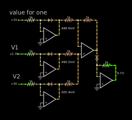
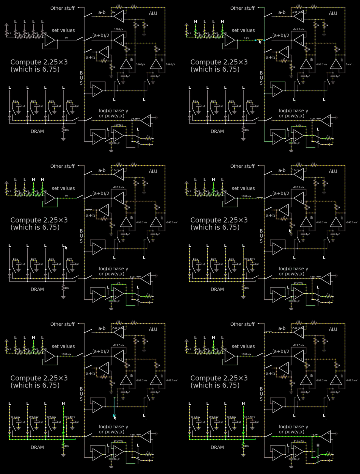
In the image above, the multiplication 2.25 × 3 is calculated which results in 6.75. The very same multiplication is made in the... monstrosity below.

The "Value for one" is the voltage reference for one. So if it is 0.1 V and V1 = V2 = 1 volt. Then the answer will be 10 V which translates to the number 100 if 0.1 V is 1.

So I decided to mux the cathode and the other pin of the 1 kΩ resistor and voilà, there's a nice logarithm and exponential function that is matched. You can see in the gif below.

enter image description here

Link to simulation.

The gif is a little bit grainy, that is on purpose to scale down 8 MB down to 2 MB. Also the gif is sped up 2x, 28 seconds instead of 55.

I know it says "log(x) in base y" and "pow(y,x)"which is not true. I confused myself with the voltage reference. It's just log and pow with some random base. The clever mathematicians will know that it doesn't matter what the base is, you can convert any log to any other log.

The number 6.7 is shown at the end at the output of the bottom right op-amp. CircuitJS truncates 6.75 to 6.7 when presenting the numbers without any mouse hovering. Placing the mouse above showed 6.69 V, so 60 mV error which is less than 250 mV and therefor acceptable. According to.. not the best simulator.


After reading Andy Aka's answer I'm unsure if another answer can beat it. I will accept his in a couple of days if no other answer beats it. I do not believe that my answer beats Andy's.

\$\endgroup\$
4
\$\begingroup\$

These things exist - Analog devices (used to?) have some multiplier ICs you can (could?) buy. They also have this excellent appnote which I definitely suggest reading.

One of the classic buildingblocks in analog design is the Gilbert Cell, named after Barrie Gilbert. It does what you seek (at least, if I understand your question correctly). Because of this multiplying capability, it is very often used as a building block in variable gain amplifiers. Think about it, if you have a building block that has a input-output relationship given as \$ V_{OUT}(t) = V_{IN, 1}(t) \cdot V_{IN, 2}(t) \$ and you set \$V_{IN, 1}\$ as the signal you want to amplify, you just need to change \$V_{IN,2}\$ to control your gain. It is also used as a mixer for the same reason.

\$\endgroup\$
3
  • 1
    \$\begingroup\$ You can still get those analog multipliers. I believe digikey even has a whole product category for them. \$\endgroup\$
    – Hearth
    Commented May 10, 2018 at 10:51
  • 4
    \$\begingroup\$ However, a Gilbert Cell depends critically on transistor matching (which is relatively easy when the transistors are part of a single die). The OP has rejected using a circuit which relies on matching of transistors, so I'm not sure this is a good answer. \$\endgroup\$ Commented May 10, 2018 at 13:24
  • 1
    \$\begingroup\$ AD633 is a 4-quadrant multiplier that outputs (X1-X2)(Y1-Y2)/10V +Z . Not particularly cheap. \$\endgroup\$ Commented May 10, 2018 at 19:51
4
\$\begingroup\$

I recently came across the "Parabolic Multiplier" circuit in a 1968 analog computer. To multiply A and B, you start with two op amps to compute A+B and A-B. Next, you need a function generator that produces X^2 (i.e. a parabola). With two function generators, you compute (A+B)^2 and (A-B)^2. You subtract the two results with an op amp, resulting in 4×A×B, which after scaling gives you A×B as desired.

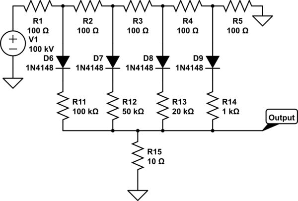
How do you get the X^2 function? An arbitrary convex function (such as X^2) can be approximated with a resistor-diode network. The idea is that each diode will turn on at a particular input voltage (controlled by the upper resistors), and provide a current (controlled by the lower resistors) to the output. The result is a piecewise linear function. (The component values below are arbitrary; I didn't work out the values for X^2.) A real function generator might have a dozen diodes for more accuracy. A function generator could be hardwired, or could have potentiometers so the user could set it to any desired function.

schematic

simulate this circuit – Schematic created using CircuitLab

The Parabolic Multiplier was considered a high-accuracy way of performing analog multiplication. A brief mention is in the Dornier 240 analog computer manual. (In German, see Der Parabel-Multiplizierer in section 9.)

\$\endgroup\$
0
\$\begingroup\$

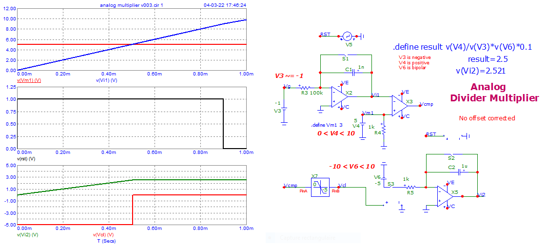
One should try a monostable (timing is the first variable) and ...
a controlled current generator (second variable).

The result is readable at the end of the pulse (sampler needed).

I used this schematic idea of the years ... 1980.

enter image description here

\$\endgroup\$

Your Answer

By clicking “Post Your Answer”, you agree to our terms of service and acknowledge you have read our privacy policy.

Not the answer you're looking for? Browse other questions tagged or ask your own question.