0
\$\begingroup\$

While reading about I2C/TWI protocol, i recognized as important part the ability to pull the signal down by any member of the communication. Thus pull-up resistors being very important here.

There are few schematics I found: http://www.cypress.com/documentation/application-notes/an50987-getting-started-i2c-psoc-1 https://cs.wikipedia.org/wiki/I%C2%B2C https://www.superhouse.tv/i2c-for-arduino/ All of these schematics contains VCC source for SDA and SCL.

What I do not get is where/what is voltage source in the case of ATMEGA & sensor (or two atmels cpus). In all schematics I have found there are only two cables - SDA ~ SDA and SCL ~ SCL.

I cannot grasp how would that work if there is not external VCC source. Sorry if the answer lies somewhere here on the stack, I could not find it.

EDIT:

As requested - links with vcc missing

In here https://howtomechatronics.com/tutorials/arduino/how-i2c-communication-works-and-how-to-use-it-with-arduino/ - there is actually both of the schematics (in the beggining one with the external voltage connected through resistor to SDA & SCL) but in the schematics with arduino and two moduls, no vcc.

\$\endgroup\$
2
  • \$\begingroup\$ "In all schematics I have found there are only two cables - SDA ~ SDA and SCL ~ SCL." Please give links to some of those schematics, as your existing links are to schematics which do show the pull-up voltage source. That will make it easier for us to explain where the (hidden?) pull-up resistors & pull-up voltage source are. It sounds like you are seeing some simplified schematics, leading to confusion. But until you show some of those confusing schematics, it's difficult to guess what exactly is confusing about the other schematics which you mention, but haven't linked. Thanks :-) \$\endgroup\$
    – SamGibson
    Commented May 16, 2018 at 15:35
  • \$\begingroup\$ Vcc is the power supply for one of the ATMegas - no extra external supply required. \$\endgroup\$ Commented May 16, 2018 at 16:41

3 Answers 3

1
\$\begingroup\$

I2C signals are externally pulled up. The current flows from the pull up. Signal pins are open drain and only set the low signal level.

\$\endgroup\$
4
  • \$\begingroup\$ Could you extend the answer. How can the current flow from pullup? It is internal pull-up resistor connected to the ground, am I right? \$\endgroup\$
    – Divisadero
    Commented May 16, 2018 at 12:42
  • 1
    \$\begingroup\$ @Divisadero: Pullups are connected to the positive rail. That is why they are pullups and not pulldowns. \$\endgroup\$ Commented May 16, 2018 at 18:36
  • \$\begingroup\$ Internal pullups are too weak. Buch stronger external are needed. Of course on the lab bench it may work with the internal ones. \$\endgroup\$ Commented May 16, 2018 at 18:44
  • \$\begingroup\$ @IgnacioVazquez-Abrams Yes, pull ups are connected to the positive rail. As here on the third picture. But there is not positive rail on the schematics I have added in edit of the question. \$\endgroup\$
    – Divisadero
    Commented May 16, 2018 at 18:49
1
\$\begingroup\$

Sometimes schematics, especially simplified diagrams, simply leave out the power and ground connections. They are assumed to be provided somehow but the detail is not important.

\$\endgroup\$
4
  • \$\begingroup\$ But there really is no external voltage source for SDA and SCL when two arduinos are talking together (for instance). So I guess i am missing something rather then schematics is not complete. \$\endgroup\$
    – Divisadero
    Commented May 16, 2018 at 12:32
  • \$\begingroup\$ @Divisadero Possibly they use the internal pull-ups on the Arduino pins in that case. \$\endgroup\$ Commented May 16, 2018 at 13:09
  • \$\begingroup\$ For sure internal pull-ups are used. But as I understand, you need external VCC for internal pull-up to keep signal high and to enable another MCU to pull it down. Where is the external VCC from then. Another MCU? It is the one pulling it down. I am lost. \$\endgroup\$
    – Divisadero
    Commented May 16, 2018 at 13:26
  • 1
    \$\begingroup\$ Internal pullups are much too weak for the reliable I2C work. I2C standard requires much stronger ones. It may work in the perfect laboratory conditions with the internal ones but it is not reliable. Consoder why there are so many posts like: "I2C hangs after couple of minutes", "I2C not working" etc \$\endgroup\$ Commented May 16, 2018 at 18:47
1
\$\begingroup\$

What I do not get is where/what is voltage source in the case of ATMEGA & sensor (or two atmels cpus). In all schematics I have found there are only two cables - SDA ~ SDA and SCL ~ SCL.

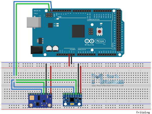
Thanks for updating the question with an example of one of the schematics that you don't understand, which I've copied below:

Arduino connected to 2 sensor breakout boards

(Source - How To Mechatronics)

In all schematics I have found there are only two cables - SDA ~ SDA and SCL ~ SCL.

Actually SDA and SCL are not the only connections in that diagram.

  • (a) There are also power and ground connections (see the red & black connections in the diagram above) from the Arduino.

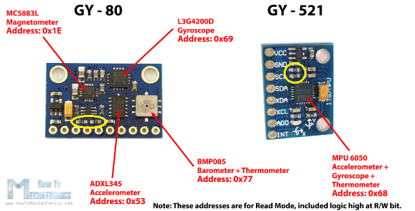
  • (b) The "sensors" you mentioned are not only sensors - they are sensor breakout boards which contain more components than just the sensors. In the case of those two breakout boards mentioned on that web page, both breakout boards also have pull-up resistors for the I2C SDA and SCL signals.

From experience, I've marked the I2C pull-up resistors by adding yellow rings on this image from that web page:

Picture showing GY-80 and GY-521 sensor breakout boards

(Source - How To Mechatronics)


Summary:

The explanation above shows where the I2C pull-ups resistors are, in the diagram you linked:

  • There is a power source (from the Arduino) to the sensor breakout boards, to power the sensors and to be available to the I2C pull-up resistors; and

  • Both of the sensor breakout boards have got I2C pull-up resistors fitted on them, even though these resistors were not shown separately, like on the earlier links in your question.

    This is partly a limitation of the "Fritzing" diagram you were looking at, which shows the physical breakout boards but not the components fitted on them, like the I2C pull-up resistors.

(There are some cases, where you would need to manually change the I2C pull-up resistors which were originally fitted on such breakout boards, especially when connecting multiple breakout boards on the same I2C bus. That decision depends on factors such as the length of the bus, the I2C clock speed, the I2C pull-up voltage and the specific resistor values originally fitted on the boards.)

\$\endgroup\$
4
  • \$\begingroup\$ So this will work, but if two MCUs would would be connected, there would be special positive rail needed? There is no need in this case as it is alredy handled by the sensor circuit... \$\endgroup\$
    – Divisadero
    Commented May 16, 2018 at 19:10
  • \$\begingroup\$ @Divisadero: there is no "special" positive rail needed. The pull-up resistors would connect to the same positive supply as the microcontrollers. \$\endgroup\$ Commented May 16, 2018 at 19:24
  • \$\begingroup\$ @Divisadero - "if two MCUs would would be connected, there would be special positive rail needed?" Unfortunately I don't understand exactly what you mean, since the web page you added doesn't show two MCUs. Please can you add a diagram of your proposed configuration and explain why you mention a "special positive rail"? Do you understand the concept and challenges of I2C multi-master configurations? If you really want to have two MCUs on one I2C bus, you need to understand those concepts too (which are out-of-scope for this question). \$\endgroup\$
    – SamGibson
    Commented May 16, 2018 at 19:24
  • 1
    \$\begingroup\$ I guess i really miss sometging. Doesnt matter, thank you very much for your help, but I have to return to study :) \$\endgroup\$
    – Divisadero
    Commented May 16, 2018 at 19:37

Your Answer

By clicking “Post Your Answer”, you agree to our terms of service and acknowledge you have read our privacy policy.

Not the answer you're looking for? Browse other questions tagged or ask your own question.