4
\$\begingroup\$

Consider:

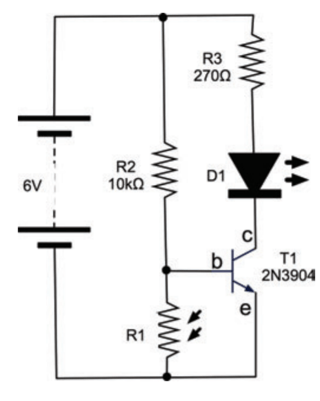
The circuit here works based on the resistance of the LDR. I don't understand how it exactly works. It's said when the resistance in the LDR is high, current flows through R2 and the base of the transistor. Which direction would current flow?

I know the convention is it flows from the positive of the battery. But from the explanation it confuses me that current is flowing from the negative terminal. And if the convention is from the positive, shouldn't the current skip R2 and go through the path of lowest resistance which is R3?

\$\endgroup\$
3
  • 9
    \$\begingroup\$ I really hate the "current follows the path of lowest resistance" expression because many beginners see an "only" in there somewhere. Current follows all possible paths, with the lower resistance paths carrying higher currents than high resistance paths. \$\endgroup\$ Commented Jun 1, 2018 at 19:54
  • \$\begingroup\$ ^^ changed my answer to reflect this changed "non" to "much less" for accuracy sake \$\endgroup\$
    – CapnJJ
    Commented Jun 1, 2018 at 19:56
  • \$\begingroup\$ R1 is a resistor that goes down with increased illumination, yes? So if there is no light, R1 is very high, leading to the current "wanting" to go through b, thereby enabling the connection between c and e. The high R2 means that even under full light, not much current is lost over R2 and R1, and on low light not much current passes through b, protecting it --- My memento for current direction is, for batteries: From the longer bar to the shorter one, because the bar 'has' more to give; and for diodes/transistors: Into the 'funnel' works, against the 'wall' (bar of diode sign) does not work. \$\endgroup\$
    – loonquawl
    Commented Jun 2, 2018 at 8:19

4 Answers 4

9
\$\begingroup\$

For reference and to protect against future edits, here is the circuit being described:
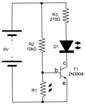
When analyzing such things, it can be helpful to consider the limiting cases. In this example, they are the LDR (R1) being a short and being infinite. Let's examine each case.

When R1 is a short, then the B-E voltage of the transistor is 0. That keeps the transistor off. That means no collector current will flow, so the LED (D1) won't light.

When R1 is open, current can flow into the base of T1 thru R2. Figure about 700 mV for the B-E drop of T1, which leaves 5.3 V across R2. By Ohms law, the current thru R2 is therefore 530 µA. That is also the base current, since that is the only place the current thru R2 can flow.

If T1 is saturated (we'll check this shortly), then figure the collector is at about 200 mV. If this is a typical green LED, it drops about 2.1 V when normally lit. That leaves 3.7 V across R3. That results in 14 mA thru R3, which is also thru D1. 14 mA should quite nicely light any ordinary indicator LED.

That was assuming T1 is saturated. Let's see what gain it would need for that to be true. We already know the collector current would be 14 mA, and that the base current is 530 µA. That comes out to a minimum gain requirement of 26. Just about any small signal transistor can do that at these current levels, so T1 is in fact saturated.

So to review, D1 is off when R1 is shorted, and nicely lit when R1 is infinite. Somewhere in between there is a transition region between full on and full off.

This circuit "works" if the LDR was chosen so that its resistance is somewhat below the transition point when light, and somewhat above when dark. Since you haven't given any particulars about the LDR, we can't say if it's light and dark resistances are suitable for this circuit. However, the basic idea is workable for a crude "night light".

A better circuit adds some positive feedback, or hysteresis. That causes the circuit to snap between the on and off states. For more information, see my answer to a similar question at https://electronics.stackexchange.com/a/53681/4512.

\$\endgroup\$
1
  • 1
    \$\begingroup\$ Very new to electronics so I'm still trying to make sense of your explanation and I seem to be getting there. Thanks so much. \$\endgroup\$ Commented Jun 1, 2018 at 21:23
2
\$\begingroup\$

R1 and R2 form a voltage divider. If R1 (the LDR) has a sufficiently low value, the transistor base will be held at a low voltage so the transistor will not conduct. When R1 has a high resistance, current will flow from the R1/R2 junction into the base of the transistor, allowing the transitor to conduct, and lighting the LED.

Try to think in terms of Conventional (positive) current - it flows in the direction of the arrow in transistor and diode symbols (except Zener diodes, which are used "backwards" - arrow pointing against the conventional current direction).

\$\endgroup\$
1
  • \$\begingroup\$ Thanks, this answer really helped me figure out the whole process in a much simpler way. \$\endgroup\$ Commented Jun 1, 2018 at 21:21
0
\$\begingroup\$

Google "hole flow versus electron flow"... electron flow is more prevalent in teaching/usage, but I learned hole flow in the US Navy (~1985), and had to "flip" my thinking when I went to college afterward... especially transistors... all of a sudden they worked "backward"

resistance in LDR is high current flows through R2 and the base of the transistor

I think your question setup answers your question(?) If LDR resistance is "much greater" than R2, R3 will have "much less" current flow through it. Maybe KCL/KVL loops prove this(?)

\$\endgroup\$
2
  • 2
    \$\begingroup\$ We usually call the positive current concept "Conventional Current". We don't care what, if anything, actually moves, but by convention assume that current is a flow of positive charge. I think conventional current is more widely taught and used than electron current. \$\endgroup\$ Commented Jun 1, 2018 at 19:51
  • 1
    \$\begingroup\$ Thanks looked into the hole flow and electron flow concept and my understanding is getting much better. \$\endgroup\$ Commented Jun 1, 2018 at 21:22
0
\$\begingroup\$

It is not necessary to consider which direction current flows: positive to negative or vice versa. However, whichever direction is chosen, it is necessary to be completely consistent: If current is considered to flow from positive to negative, then it works in the "positive universe". Perform whatever analysis calculations desired.

If one then switch universes for the same circuit, and perform the same analysis, the results are exactly the same.

Likewise, when considering current flow through a point, one can either assume inflows are positive and outflows negative; or vice versa. As long as the choice is absolutely consistent throughout the circuit, one obtains correct results.

\$\endgroup\$

Your Answer

By clicking “Post Your Answer”, you agree to our terms of service and acknowledge you have read our privacy policy.

Not the answer you're looking for? Browse other questions tagged or ask your own question.