0
\$\begingroup\$

I am trying to figure out if the equivalent resistance (or similarly conductance) of a resistor network can be calculated using Qucs (as opposed to solving the Kirchhoff equations directly, or doing the numerical Star-Mesh transform on the network).

For instance if we know the graph/network characteristics, that is, the vertex set (i.e. how many nodes), the edge (bond) set and the resistance values corresponding to each bond (so between a chosen pair of vertices),

  • How can we input the resistor network as such into Qucs? (can netlists be used for this purpose?)
  • Assuming the above point is possible, can we then use Qucs to estimate the equivalent resistance of the network? That is, can we set up a Qucs simulation for this type of calculation? (e.g., using a fixed voltage generator in an AC simulation?)

Being a complete novice to Qucs, any hints at any level, be they basic or advanced, would be extremely valuable to me. Unfortunately, in the existing Qucs tutorials I haven't found any examples pertaining to the above type of calculations.


In case you prefer to answer with a working (dummy) example, here's a network we can work with:

Example network for testing purposes: 4 nodes only, labelled from one to four. The only bonds in the network are: {1,2} with resistance 5 ohms, bond {1,3} with resistance 10 ohms and bond {2,4} with resistance 5 ohms. And we're trying to find out the resistance between the input and output.
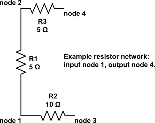
schematic

simulate this circuit – Schematic created using CircuitLab

\$\endgroup\$
9
  • \$\begingroup\$ In your example, what 2 nodes do you want to find the equivalent resistance between? \$\endgroup\$
    – The Photon
    Commented Jun 6, 2018 at 15:43
  • \$\begingroup\$ @ThePhoton Sorry I forgot to mention, between nodes 1 and 4. \$\endgroup\$
    – user929304
    Commented Jun 6, 2018 at 15:50
  • \$\begingroup\$ (1)---5 ohms---(2)---5 ohms---(4) sounds fairly basic and node (3) doesn't appear to play a part. Sounds like 10 ohms to me. \$\endgroup\$
    – Andy aka
    Commented Jun 6, 2018 at 16:01
  • \$\begingroup\$ @Andyaka Right, but it's made to be trivial so that we can easily check whether the result from Qucs is correct, in other words this post is aimed at learning how to do these resistor network calculations using Qucs (admittedly, I don't even know how to input the network using a netlist). Once learned then I can use it for larger networks. \$\endgroup\$
    – user929304
    Commented Jun 6, 2018 at 16:04
  • \$\begingroup\$ I'm unsure how valid this question is being as it about how to use a software package. I mean, many questions are closed down when people ask if their mobile phone can do this or that. They are closed on the basis that questions on electronic devices (i.e. things you can purchase) are off-topic. \$\endgroup\$
    – Andy aka
    Commented Jun 6, 2018 at 16:08

1 Answer 1

0
\$\begingroup\$

You certainly can use any simulator to determine transfer function or impedance.

For DC, put a current source and a voltmeter between the two nodes "in,out" at any value such as 1mA or 1A ( won't burn up a simulator, lol)

By the way, this is how DMM's work in the resistance scale, and some change current scales e.g. from 100uA to 10mA for different R ranges. Some precision RLC meters use Sine wave current sources, and others use pulse decay time constant method.

Req=V/I

The best tool is the one you can master easily then move up to a better tool.

\$\endgroup\$
7
  • \$\begingroup\$ Thank you very much, I think I roughly see what you mean. I've only heard of the tool Qucs (which I am trying to learn about), do you know of other open source projects that would be easier to get started with? or possibly showing how one such simulator can be used for the dummy example in the post? Any tips would help me a lot. \$\endgroup\$
    – user929304
    Commented Jun 6, 2018 at 15:53
  • \$\begingroup\$ There are dozens of free electronic simulators, Qucs is a good one start with. many variations of Spice LT,V are also rans. Some have pre-designed standard circuits. \$\endgroup\$
    – D.A.S.
    Commented Jun 6, 2018 at 15:56
  • \$\begingroup\$ Would you be so kind to showcase one example of doing so (maybe for the example in the post, although it's trivial network) with one of the tools (Qucs e.g.)? If you don't have time, I'd understand. \$\endgroup\$
    – user929304
    Commented Jun 6, 2018 at 16:05
  • \$\begingroup\$ Can you try drawing it first with this site's free schematic editor?, we dont think in node numbers and yours are not labelled \$\endgroup\$
    – D.A.S.
    Commented Jun 6, 2018 at 16:07
  • \$\begingroup\$ Brilliant, didn't know the site had such neatly designed built-in editor. I've tried to design the example schematically, hopefully it matches correctly what I had written. \$\endgroup\$
    – user929304
    Commented Jun 6, 2018 at 16:18

Your Answer

By clicking “Post Your Answer”, you agree to our terms of service and acknowledge you have read our privacy policy.

Not the answer you're looking for? Browse other questions tagged or ask your own question.