0
\$\begingroup\$

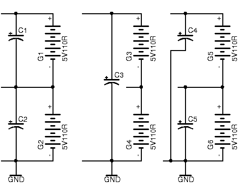
I'm trying to figure out if I can improve the elimination of noise. I always decouple my IC's by connecting VCC and ground together with a 100nF ceramic capacitor, But I'm curious. In each picture below, assume the top battery is 2V higher than the lower battery and all batteries are fully charged. Also assume the capacitors are all electrolytic and are at least 10uF and can handle 16V. The mid-point between the two sets of batteries deliver the lower voltage that's needed.

Which of the circuits shown is the best for decoupling?

Should I follow the left-most circuit where I decouple each battery set individually?

or should I follow the middle circuit where I combine the sets together first before decoupling as if all batteries are one big voltage source?

or should I just continue to follow the last circuit where each voltage point above 0 gets grounded via a capacitor?

or should I combine any of those circuit ideas?

Also, there are no negative voltages.

circuit

\$\endgroup\$
3
  • \$\begingroup\$ Are the batteries more than a few inches from the circuit? Is the load steady or intermittent - on either or both rails? What problem arises from the noise? Are there regulators between the batteries and the circuitry? \$\endgroup\$ Commented Jun 9, 2018 at 21:22
  • \$\begingroup\$ Load will always be steady. I'm asking more of this because I'm also looking for ways to eliminate ground loops as well and if decoupling from voltage to voltage adds benefit then I'd do that \$\endgroup\$ Commented Jun 9, 2018 at 22:15
  • 1
    \$\begingroup\$ The batteries aren't the thing that needs decoupling, it's the ICs - capacitor should be as close to them as possible. \$\endgroup\$
    – pjc50
    Commented Jun 9, 2018 at 22:56

3 Answers 3

1
\$\begingroup\$

Could be that I have a completely wrong assumption on how decoupling capacitors work, but here goes:

You have to analyze the current loops and place decoupling capacitors in the loop to help reduce the size of the loop.

So let's assume you have some ICs working on the top rail and some working on the bottom rail. So you want decoupling on both rails. This approach would rule out the middle suggestion, there is no decoupling on the bottom rail.

The left approach helps if you have currents which will flow from the top rail to the bottom rail, but I guess most of the ICs will have current loops from their supply to ground. So the left solution will provide decoupling for the top rail and the bottom rail, but the top rail sees a series connection of capacitors to ground which will result in a lower capacity and thus might reduce the effectiveness of the decoupling.

So I'd vote for the right approach because that provides decoupling on both rails with the actual capacity of the capacitors for both rails.

I'd also say that an electrolytic cap alone will not provide very good decoupling as they have higher ESR and ESL values, which is not what you want in decoupling, you want to provide a very low impedance path for the noise to go. So placing a ceramic cap (or several with different capacities for different noise frequencies) as close as possible to the IC is usually a good approach. Even the capacity between the power plane and the ground plane around an IC can act as a decoupling capacitor for very high frequencies if the connection is done in a low impedance way.

\$\endgroup\$
0
\$\begingroup\$

The important bit in decoupling is low inductance. Larger capacitors have more internal ("parasitic") inductance, and longer traces do so as well.

So, your decoupling capacitors should be placed right next to the ICs, and between each voltage rail and the corresponding ground (i.e. digital supply to digital ground, and analog supply to analog ground). The size of the capacitors depends on the frequency that the IC operates at, and the range that the supply current may vary in.

For tens of MHz, a single 100n capacitor (just use a normal ceramic, no need for electrolytic) is sufficient. Faster ICs might need a 10n or 1n capacitor near the supply pin, and possibly another larger capacitor a few mm further away, where there is more space.

\$\endgroup\$
2
  • \$\begingroup\$ so theres no advantage if I connected a decoupling capacitor between say +5VDC and +3VDC on the same board? \$\endgroup\$ Commented Jun 9, 2018 at 21:17
  • \$\begingroup\$ In the best case, (close to the batteries) it does nothing. In the worst case (close to the ICs) it transfers noise between power rails. \$\endgroup\$ Commented Jun 10, 2018 at 13:12
0
\$\begingroup\$

Mike unless you know the equivalent circuit of your load and batteries , your question is pointless. Batteries are about 1000 times higher capacitance than a capacitor and in many cases much lower ESR than a 100uF cap.

Fundamentally what does “decoupling” mean?

Decoupling means the step or impulse load current follows the shorter path of least impedance. This is chiefly due to rise time dV/dt=Ic/C + I*ESR step load error.

Before you ask any question like this , all unknowns must be specified for load current spectrum(f), source impedance (f) and cap Z(f).

If don’t know it, you ought to learn it. The question is irrelevant without values on voltage error, slew rate or spectrum and acceptance criteria with defined load characteristics.

\$\endgroup\$

Your Answer

By clicking “Post Your Answer”, you agree to our terms of service and acknowledge you have read our privacy policy.

Not the answer you're looking for? Browse other questions tagged or ask your own question.