In my project I have connected multiple sensor breakout boards to an Arduino-Pro-Mini running at 3.3V and 8Mhz as follows on a fabricated pcb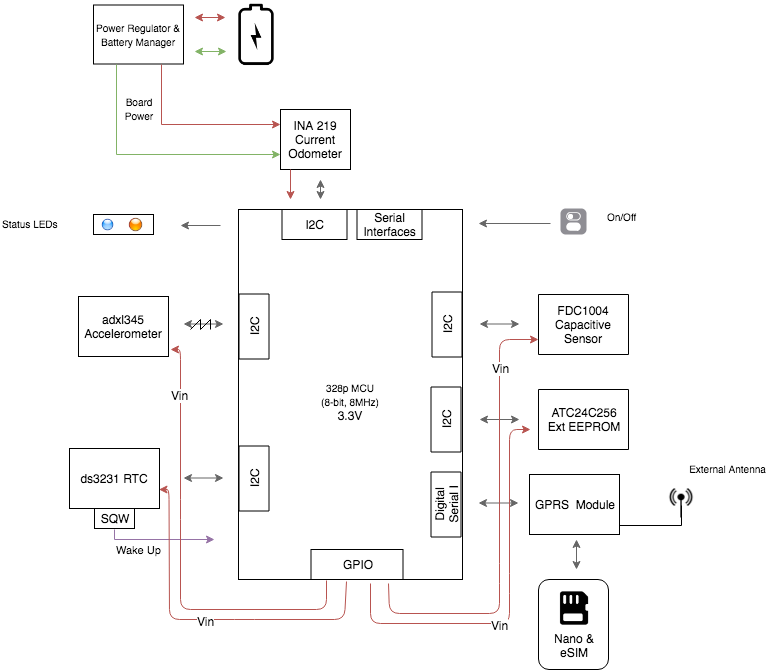
This is how the proto-pcb looks: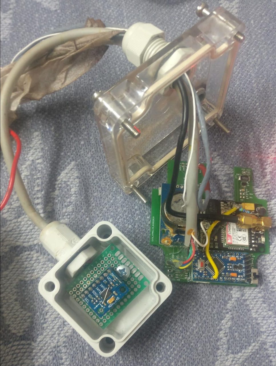
You will see that all the components are on one PCB, except the accelerometer which is a breakout board connected to the main pcb via a 1-feet cable
I am using GPIOs to power the individual breakout boards and pullup the SDA SCL lines, because before I'd designed the PCBs I'd thought that this would help me conserve power by allowing me to turn off the individual sensors when they were not in use by toggling the GPIO pins. After learning that toggling the GPIO pins could damage my i2c lines from a discussion here I decided to keep all the GPIOs permanently high and use the internal power down modes of all the individual breakouts for power conservation. I could've modified my designs and powered all the boards with Vcc, but as everything was working fine and because more importantly 30 of my pcbs had already arrived from the fab-house and the client was after my life for the pilot project, I decided to go ahead with it.
But after a week of installing 15 of these pcbs in an IP65 enclosure in a highly humid environment, 10 of the 15 pcbs stopped transmitting data. Upon inspection I found that there signs of moisture deposits inside all the boxes and in 4 of the pcbs, the i2c lines were blocked.
Upon analyzing the signal on an Oscilloscope it looked like the SDA and SCL line were fine at first, but as soon as the master tries to write on the line: 1) SDA goes from HIGH to LOW and freezes subsequently 2) SCL starts and then keeps going
This is how the SDA (red, channel 1) and SCL (yellow, channel 2) look at a timebase of 1us:
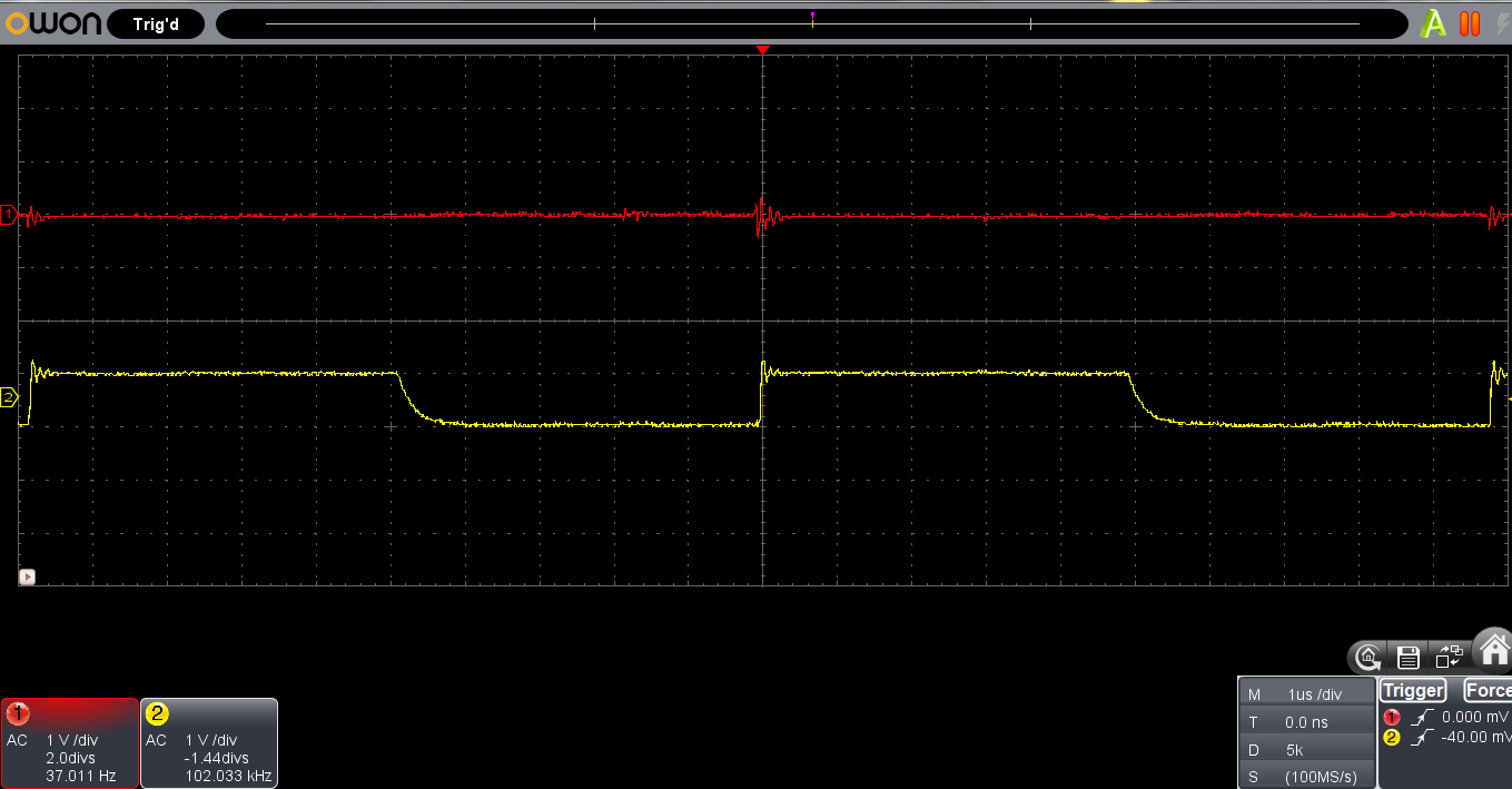 the actual DSO capture for this can be seen here
Where as, this is how they should look normally:
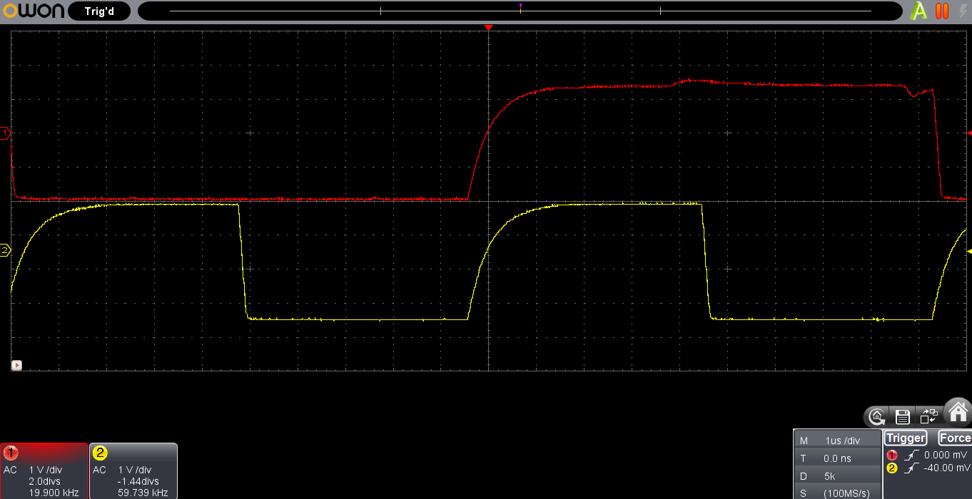 the actual DSO capture for this is no. 1 in the comments below ..
Zooming out a little bit to a timebase of 10us,
(sda-scl at 10us in a damaged pcb)
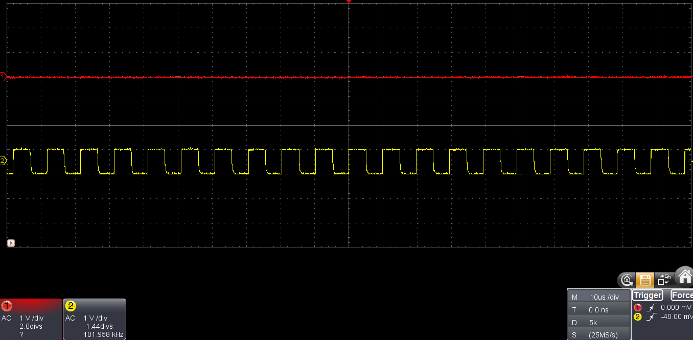 the actual DSO capture for this is no. 2 in the comments below ..
where as, (sda-scl at 10us expected in a working pcb)
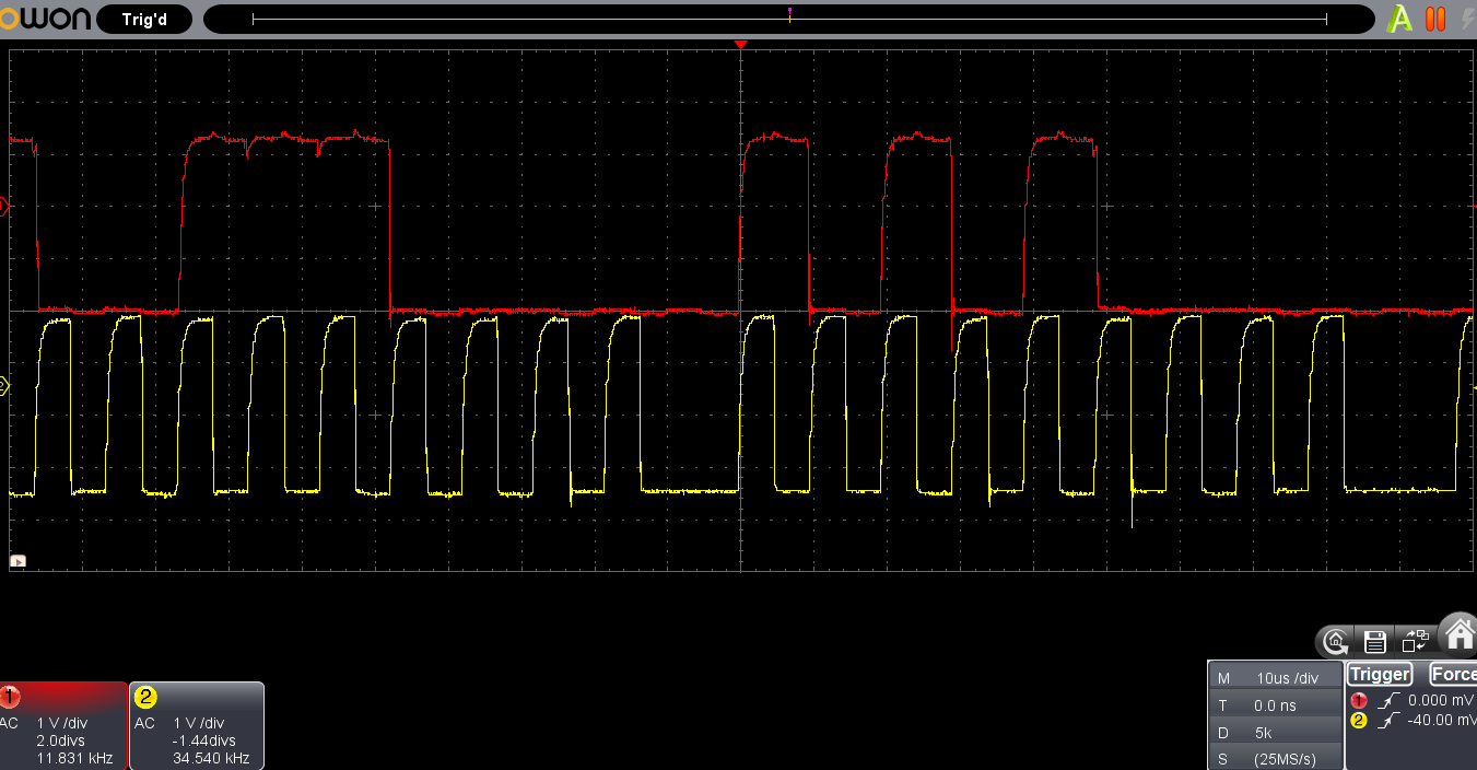 the actual DSO capture for this is no. 3 in the comments below ..
6 of the 10 pcbs which had moisture deposits inside and had stopped transmitting data had no issues and seemed to be working fine when I tried to debug them. I guess that they were in a low signal area and hence were not able to register on the network because the antenna isn't very effective anyhow.
Out of the other 4 pcbs that had their i2c lines blocked, 2 of the pcbs started working normally as soon as I de-soldered the RTC breakout board and connected all the remaining breakout boards and the sda/scl pullups directly to the Vcc line instead of the GPIOs. There was no issue with RTC breakouts or the voltage on the GPIO pins.
In one of the PCBs, the SCL pin of the accelerometer seemed to be fried, as it was pulling the entire line to low. It wasn't shorted or anything but there were some white deposits on the pins of the main IC.
Would be grateful if someone could throw some light on what could be blocking the i2c - SDA line and why did the desoldering the RTC and migrating from GPIOs to Vcc solve this issue? Has the issue been solved, or is it just temporary?
Is it possible that because of the way the GPIOs have been used to power the breakout boards, the SDA/SCL pins of one of the breakout boards could have been damaged?
