1
\$\begingroup\$

Following is the MOSFET I am using in my power supply ( Topology - forward converter): PSMN1R8-40YLC Estimated power dissipated in the MOSFET (including the switch losses) is 4 W

My intention to calculate the temperature rise in the MOSFET due to the power dissipation in the MOSFET.

Basic understanding, Tj = Ta + RΘja * Pd -------------- Eqn (1)

Tj = Junction temperature

Ta = Ambient temperature (Taking as 25 °C)

RΘja = Junction to ambient thermal resistance

Pd = Power dissipated in the MOSFET

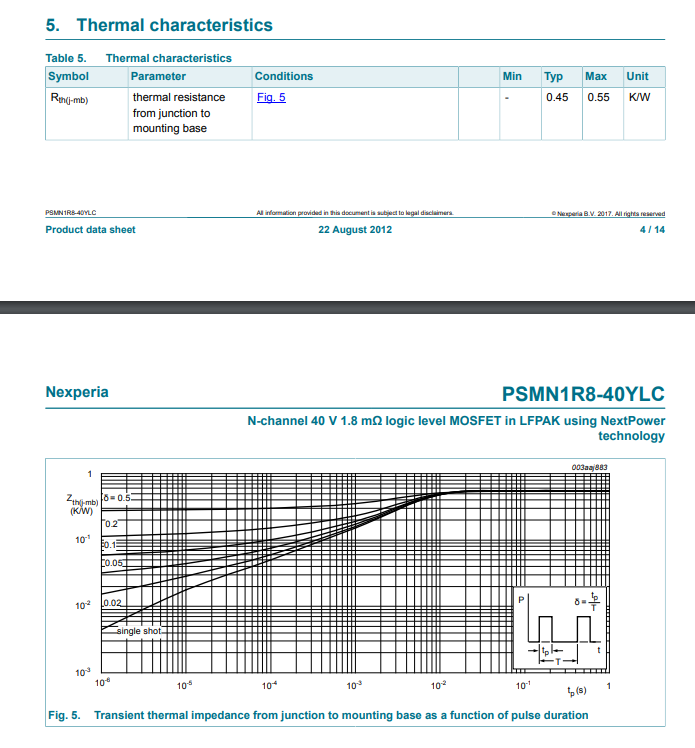
Following are the only thermal information available in the datasheet,

enter image description here

Information available is thermal resistance from junction to mounting base.

Q1) Can I calculate the junction temperature (using Eq(1)) using thermal resistance from junction to mounting base?

Q2) I understood that thermal resistance from junction to ambient is more related to PCB area and other factors, But still can we calculate the thermal resistance from junction ambient using thermal resistance from junction mounting base?

\$\endgroup\$

2 Answers 2

2
\$\begingroup\$

Q1) Yes you can, if we assume the mounting base to be at 50°C, then using 4 W dissipation and 0.55 K/W (max value) thermal resistance of junction to base we get:

Tj = 50°C + (4 W * 0.55 °C/W) = 52.2°C

Q2) Yes, the method of calculation is the same as above and the "starting point" will be the ambient temperature instead of the mounting base temperature and you simply add up the thermal resistances:

Tj = Ta + Pd * (Rth_amb_to_base + Rth_base_to_juntion)

\$\endgroup\$
6
  • \$\begingroup\$ I understood that you are assuming mounting base is at 50°C, Is this a worst case temperature taken ( I am checking whether there is an engineering logic behind this value ) or arbitrarily took it? \$\endgroup\$
    – vt673
    Commented Jul 10, 2018 at 7:03
  • 1
    \$\begingroup\$ Yes, the 50°C is indeed an assumption. The value is arbitrary, it doesn't really matter what value it is as the rise in temperature is the interesting bit, here it's only 2.2°C which is not much but assumes that the base stays at the same temperature. In practice that will be a challenge (unless the base is very large) so achieving a low base to ambient thermal resistance will be the challenge. \$\endgroup\$ Commented Jul 10, 2018 at 7:13
  • \$\begingroup\$ I would like to go with the second equation with ambient temperature of 25°C. But not sure how to get the Rth_amb_to_base :-( Can we estimate it with some assumptions? \$\endgroup\$
    – vt673
    Commented Jul 10, 2018 at 7:19
  • 1
    \$\begingroup\$ Indeed the Rth_amb_to_base is the tricky one. If you would use a heatsink the datasheet lists the value. If you use a copper plate (on the PCB) there are calculators for that. Also important is the ambient temperature, if the PCB is in a closed (plastic) box heat can build up. If the case is metal you might use the case as a heatsink. You need to dissipate 4 W, not that much but it can be a challenge in a small space. In a smartphone 4 W for a couple of minutes is enough to make it quite warm already. \$\endgroup\$ Commented Jul 10, 2018 at 8:00
  • 1
    \$\begingroup\$ Sure, there are calculators available. I do not know which to recommend. It appears TI also has a tool: ti.com/adc/docs/midlevel.tsp?contentId=76735 \$\endgroup\$ Commented Jul 10, 2018 at 9:00
2
\$\begingroup\$

Can I calculate the junction temperature (using Eq(1)) using thermal resistance from junction to mounting base?

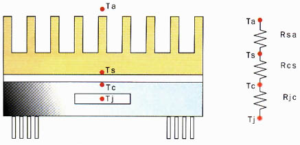
You can but the mounting base is assumed to have perfect heat dissipation qualities i.e. it is asssumed that the base remains at the ambient temperature. In reality, the mounting base will also have a thermal resistance and this will be in series with the device's thermal resistance: -

enter image description here

In the picture above the total thermal resistance to ambient is: -

Rjc + Rcs + Rsa

Where Rjc is the thermal resistance quoted in the data sheet for the MOSFET. Rcs is the small thermal resistance due to mounting the MOSFET to a heatsink and Rsa is the heatsink's thermal resistance to air and this also assumes a certain air flow and optimum positioning of the heatsink.

Picture source.

I understood that thermal resistance from junction to ambient is more related to PCB area and other factors, But still can we calculate the thermal resistance from junction ambient using thermal resistance from junction mounting base?
The above explanation I gave should make this clearer now but don't assume local ambient is going to remain at 25 degC - it depends on removal of heat being reasonable.

Also be aware that the device you have chosen is intended for switching applications where the gate-source voltage is intentionally set to turn on the MOSFET near-completely. If you are considering using this MOSFET for current limiting or linear applications you need to be careful about thermal runaway when the gate voltage is below a few volts (Spirito effect).

\$\endgroup\$

Your Answer

By clicking “Post Your Answer”, you agree to our terms of service and acknowledge you have read our privacy policy.

Not the answer you're looking for? Browse other questions tagged or ask your own question.