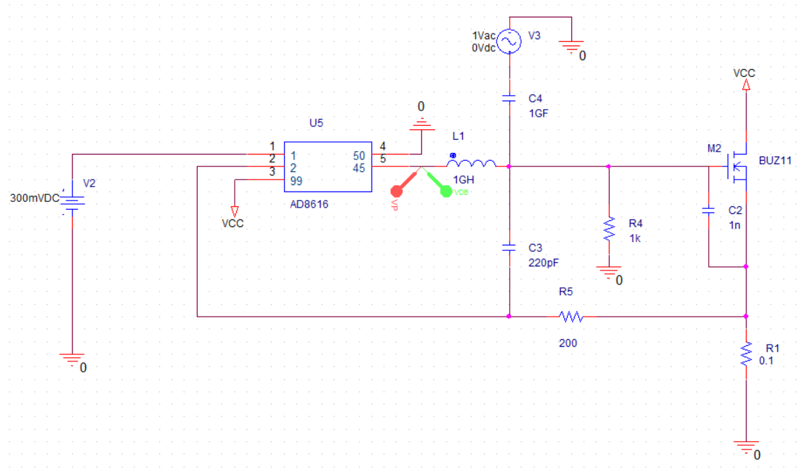
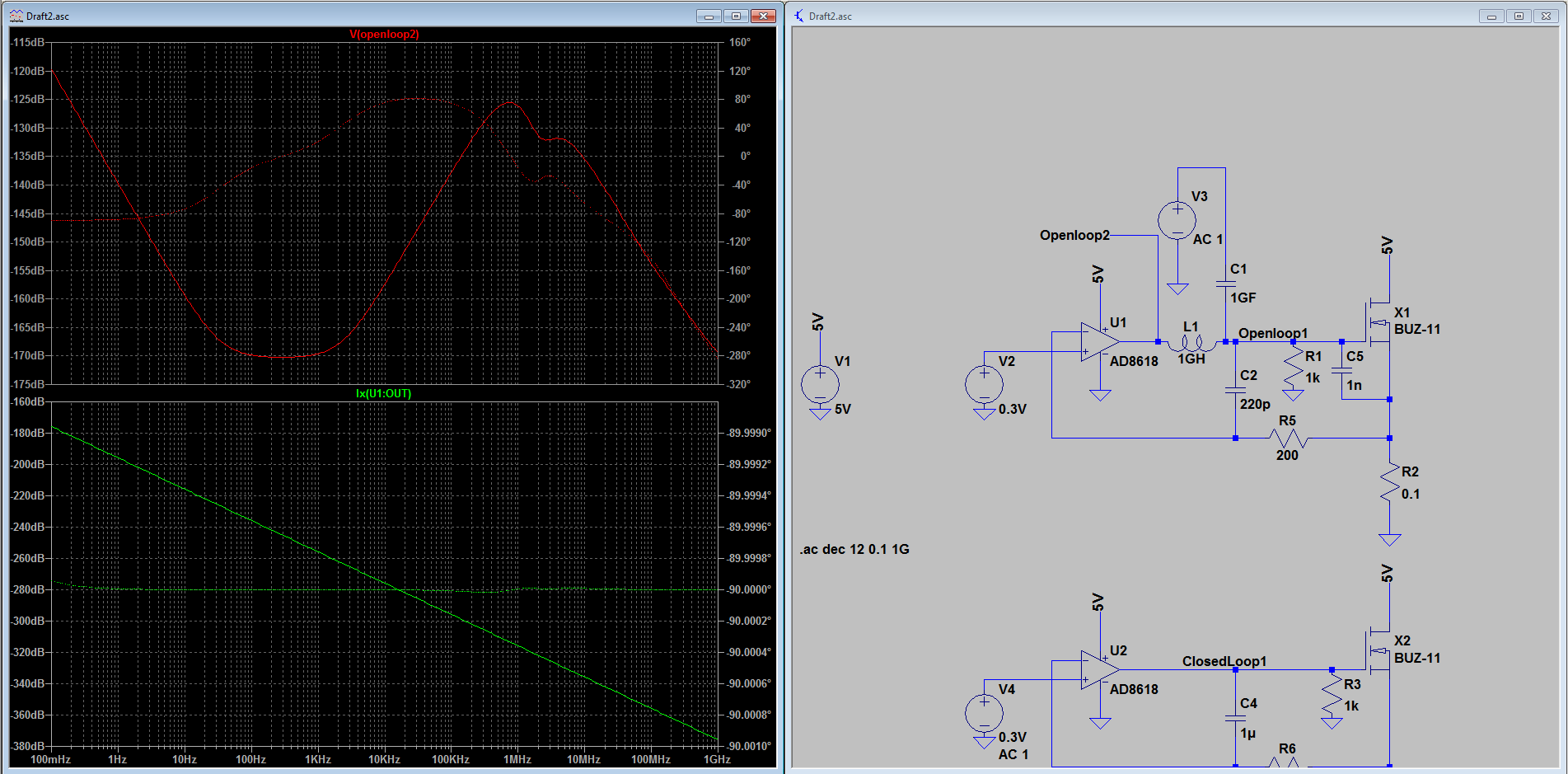
I've tried to build this opamp/mosfet current source, and been struggling to make it stable. When simulating the open-loop gain in PSpice. I've set it up like this, which should give Vout = -AB at the output of the opamp.
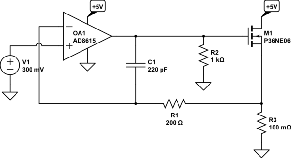
simulate this circuit – Schematic created using CircuitLab
And it looks to have a huge phase margin on the plot:
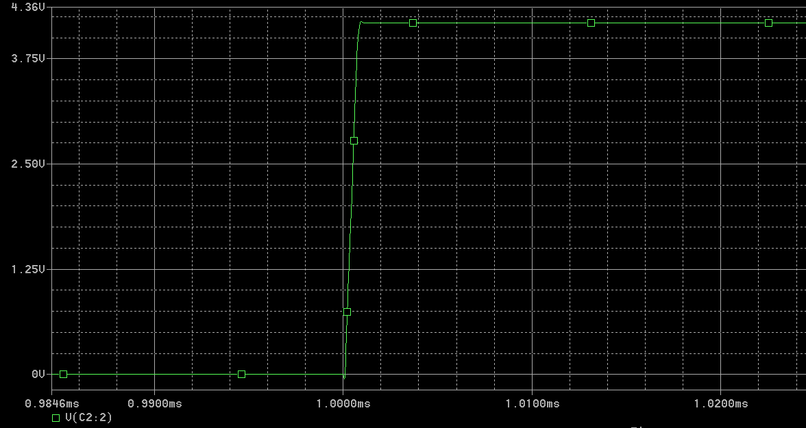
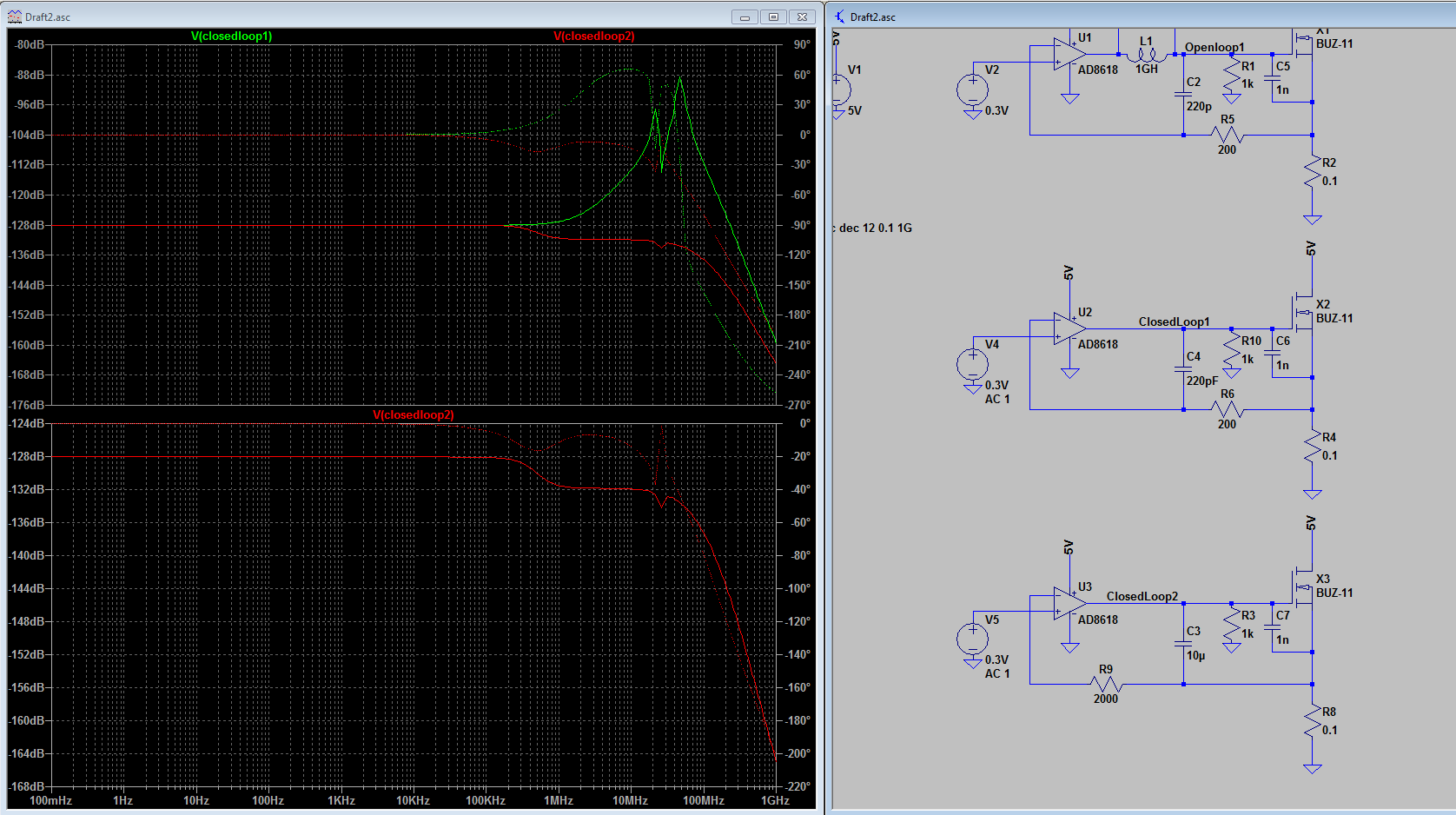
Which also shows if I step the input with a 1 ns rise pulse, that it is very stable(measured at the output of the opamp):
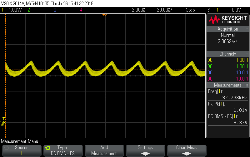
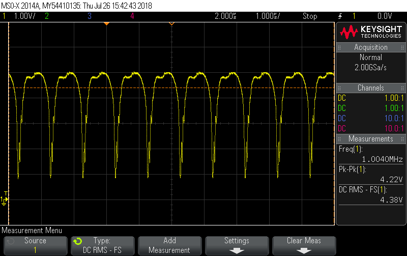
But unfortunately it is very unstable on the prototype PCB that I made. The first picture is when the input voltage is 0, or below 10 mV. The second picture is when I increase the voltage to around 70 mV at the input:
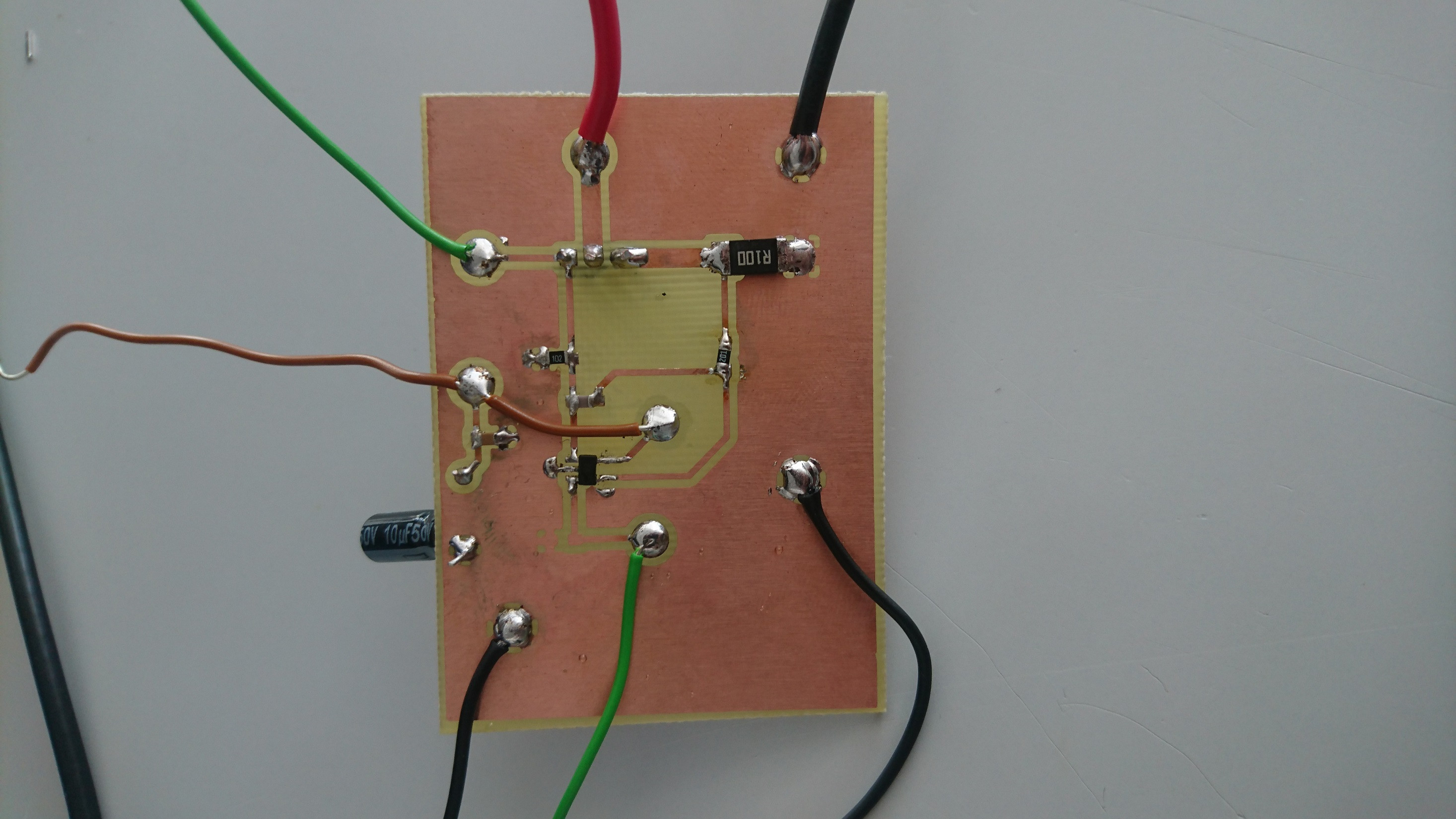
Here is a picture of the PCB:
I could not route the 5 V for the opamp on the single sided PCB, so I made a small jumper. At the input of the 5 V there is a 10 µF electrolytic and a 100 nF ceramic as a bypass.
The green wire at the bottom is the input to the opamp. The other green wire is measurement at the gate of the opamp.
How can I simulate this circuit correctly?
How can I stop the oscillations in my circuit?
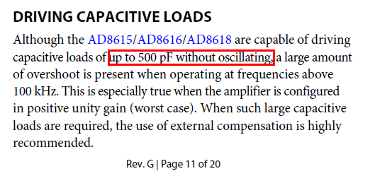
EDIT: I forgot to mention that I added C2 because the mosfet I'm using (ST P36NE06) has more input capacitance than this BUZ11 FET has.

