5
\$\begingroup\$

I've been working on a project messing around with the YM2612 soundchip and hooking it up to a microcontroller. I'm able to drive the chip, but I'm having a little trouble with the audio part of the circuit.

I have a 10kΩ pulldown resistor on one of the outputs of the chip (I'm only testing this output for the time being). I've noticed that there appears to be some kind of voltage offset at the output of the chip. I'm still learning about electronics, so I'm not fully sure how to look this up, other than what I think is messing with the "voltage bias", but in most cases, it seems to be about raising the signal's offset instead of lowering it. The signal seems to be the normal audio signal, but instead of being based around 0v as the center, it's about 2.8ish volts or so.

I was trying to amplify the signal since it's a very low audio signal, but with the voltage offset, I feel like using an op-amp just to amplify the signal, with it always being at ~2.8v I won't be getting as much gain as I'd like to (using a 5v supply for this). I'm sorry if some of my terminology is mixed up. I'm happy to elaborate on anything I might have forgotten, but would really love any help or advice you can provide on how to handle the audio output circuit. Oh, btw, I don't want to directly hook this up to a speaker or anything, this is just about obtaining line level for headphones or something of that nature.

\$\endgroup\$

1 Answer 1

6
\$\begingroup\$

The analogue outputs from this chip will have a DC voltage of approximately 50% the DC supply voltages so that the output can produce superimposed AC waveforms without unreasonably clipping.

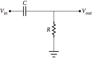
This is standard for most electronic audio chips and most signal processing chips. You need to connect to an amplifier using a DC block circuit so that the resulting signal is centred around 0 volts: -

enter image description here

The capacitor value would be a few micro farads and the resistor would be about 10 kohm.

If you can provide more details of the Yamaha chip (i.e. a data sheet link) and explain what amplifier you are considering, closer values can be obtained.

\$\endgroup\$
9
  • \$\begingroup\$ Sadly there isn't much information available about this chip as far as what you'd expect to see in a normal datasheet. This is about the only thing that comes up for it. There is some other documentation online but it's just about the data and the registers of the chip itself. datasheetspdf.com/pdf-file/865751/Yamaha/YM2612/1 \$\endgroup\$ Commented Aug 3, 2018 at 20:20
  • \$\begingroup\$ I've been using a LM741 as a buffer for the signal and not put too much strain on the DAC. I'm considering using a LM386 as that seems to be what a lot of people seem to use / prefer for a project like this. The way I've been connecting the audio signal to the LM741 is just using a 10k pulldown resistor in parallel to ground and the signal just goes into the non-inverting input after that. I think I had tried putting a capacitor in series with this when I was looking things up but I'm pretty sure it was electrolytic. Does the type of cap / polarized v non-polarized make a difference here? \$\endgroup\$ Commented Aug 3, 2018 at 20:29
  • \$\begingroup\$ Use a non polarised capacitor and post the circuit including power rail information. \$\endgroup\$
    – Andy aka
    Commented Aug 3, 2018 at 20:38
  • \$\begingroup\$ This is what I currently have built up on my breadboard. I simplified the data bus and control pins to reduce clutter but they are directly connected for the time being but will end up using a shift register or something to reduce the pins. gyazo.com/a0f9f5cc1164f50723031f398440bd10 \$\endgroup\$ Commented Aug 3, 2018 at 23:32
  • 1
    \$\begingroup\$ I realized that I don't actually need a negative rail and can just do what the yamaha chip is already doing. I can remove the dc offset before feeding the signal into an audio op amp but then recenter that audio back around half the operating voltage then filter the output with some caps. That way I can feed a signal that is stronger but have the power of the audio amp IC to provide a strong signal \$\endgroup\$ Commented Aug 27, 2018 at 19:50

Your Answer

By clicking “Post Your Answer”, you agree to our terms of service and acknowledge you have read our privacy policy.

Not the answer you're looking for? Browse other questions tagged or ask your own question.