4
\$\begingroup\$

I found an expression that explains how a circuit with op-amp responses to a distortion: enter image description here

$$y = \frac{1}{\beta}x + \frac{\delta}{A\beta} $$

Now consider the circuit:

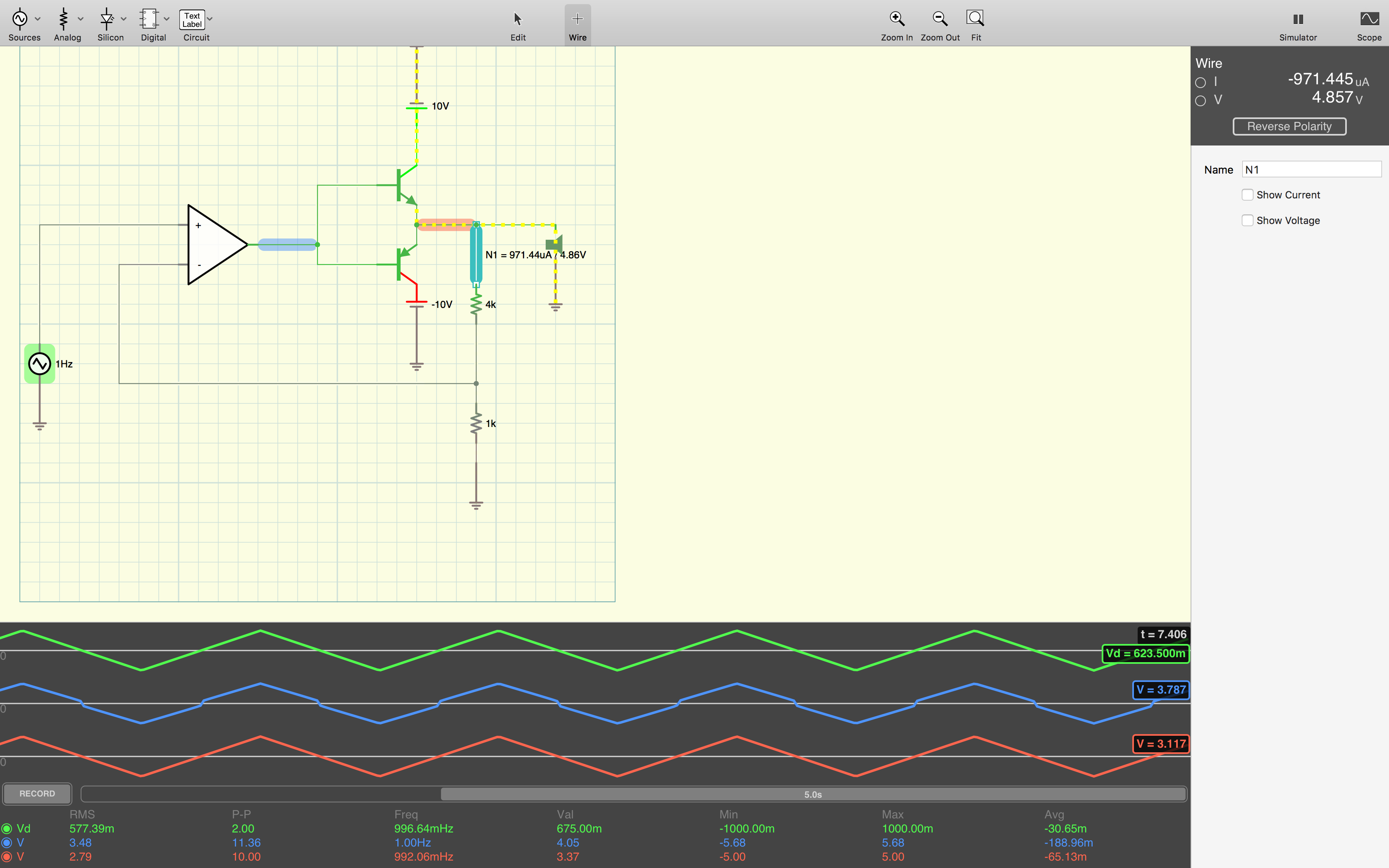
enter image description here

Here, the green, blue and red waves represent input, op-amp out put voltage and out put voltage respectively.

I know, the cross-over transistors introduce distortion, equivalent to the \$\delta\$ in my expression. I expect to get as the maximum voltage of about 5.7 volts at the out put (node N1), but i observe the maximum voltage of exactly 5 volts. So no distortion at the output at all. And i can't explain it. I mean the voltage at N1 is equivalent to voltage y at my initial circuit, and y includes the distortion, however that's not the case at the second circuit.

\$\endgroup\$
1

2 Answers 2

6
\$\begingroup\$

Indeed you get (almost) no distortion at the output because it is suppressed by the loopgain. You do see distortion (actually pre-distortion) at the output of the opamp. The opamp is compensating for the distortion of the output stage.

It is unclear how large the gain of your opamp (model) is but my guess is that it is very high (> 1000) that results in a high loopgain and thus high suppression of the distortion.

So lower the gain of the opamp to 10 or 100 and see what happens.

Pro tip: Don't use a triangle wave as input signal but a sinewave then plot the spectrum (use FFT function) of the signals. That way you can get more accurate / insightful numbers for the distortion and also "see" lower distortion values. For example 1% THD is impossible to see in a time plot but shows up in a spectral plot as peaks up to -40 dBc.

\$\endgroup\$
2
  • \$\begingroup\$ Great, I'm almost there, but, as you and i can see and you said, we see the pre-distortion right at the out out of op-amp, and as you suggest, the loop gain suppresses the distortion, i agree, but between the output of op-amp (amplified signal + distortion) and the output stage (amplified signal + almost no distortion) there is absolutely nothing that op-amp can do there is only this cross-over transistors configuration. Clearly i'm confusing things, but i don't see it. Thank you \$\endgroup\$
    – user140508
    Commented Aug 6, 2018 at 11:33
  • 2
    \$\begingroup\$ there is absolutely nothing that op-amp can do No, there is. The opamp amplifies the error Vin-Vout and uses that as compensation for any distortion. See your formula: as A increases the transfer becomes equal to 1/beta. As long as the opamp has enough gain at it's disposal, it will supress any distortion in the forward path of the loop \$\endgroup\$ Commented Aug 6, 2018 at 12:09
2
\$\begingroup\$

The classic large-dead-zone audio amplifier, using two bipolars of NPN and PNP polarity with the bases tied together and to the servo-amplifier (negative feedback amplifier) output, exhibits a 2 * Veb = 2 * 0.7 volt or 2 * 0.8 volt dead-zone. The default UA741 opamp has 0.5 volt/microsecond slewrate; to slew those bases over the 1.6 volt dead-zone requires over 3 microSeconds.

This slewing time, when the opamp is only SLEWING and not able to respond to any input-output errors, is the duration of the impulse function your diagram shows injected at the output.

As bimpelrekkie suggests, change the input signal. I suggest you use a 20,000 Hertz sinusoid of amplitude 20 volts peak-peak. With 50 uSec period, and 3uSec dead-zone and 2 dead-zones per cycle, you should be able to visually notice the distortion.

Your question regards how the transistors "dampen" the distorton. In truth, the loop is doing its job, the negative feedback loop is doing its job.

Increase the frequency to 50,000 Hz or 100,000Hz.

And inject some interesting "music" such as massed fiddles, with all those strings being tuned by the players' ears. Inject 1,000 Hz and 1,010 Hz and 1,020 Hz at the same time, and examine the FFT. Gather a 500 millisecond of samples, which provides 2 Hertz frequency-binning, so you'll clearly see the intermodulation.

The irritation of dead-zone during cross-over events comes from the wide-band nature of the IMPULSE function (very narrow in time) model of cross-over. The ear is hearing spikes in the music, spikes that are not in the original program material, spikes that are dependent on when various sinusoids interact to generate a zero-crossing.

Why does THD not capture this phenomena? Because using a single-tone test results in the cross-over error spikes occurring only at the zero-crossings, and all the energy is harmonically related to the single-tone.

Multi-tone tests bring out the non-harmonically-related hash (randomly timed) spikes.

\$\endgroup\$

Your Answer

By clicking “Post Your Answer”, you agree to our terms of service and acknowledge you have read our privacy policy.