1
\$\begingroup\$

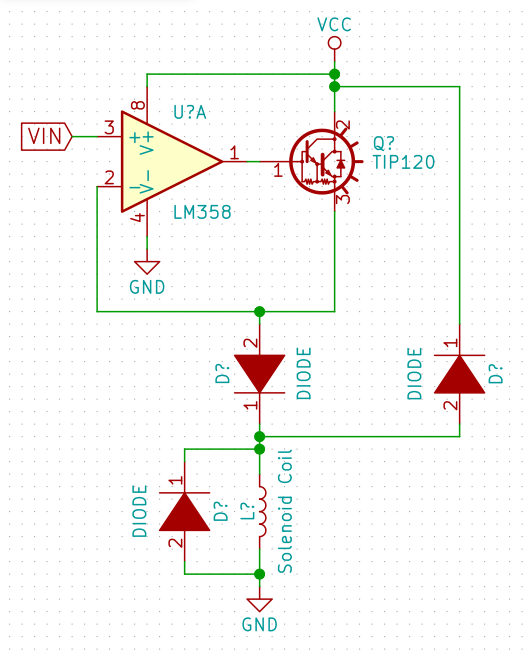
I am using a darlington buffered op-amp to drive a solenoid motor at variable voltages (for variable speeds of actuation). Here is my circuit as it is now:

Solenoid Circuit

I am wondering which of the two flyback diodes (from coil to GND and coil to VCC) are necessary to drain flyback current from the solenoid, or if perhaps a resistor across the solenoid is necessary.

The diode from the op-amp output to the coil is to prevent flyback from interacting with the op-amp output. This one I am certain is necessary from hands-on testing.

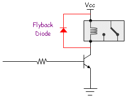
Normally I see this as a flyback circuit:

Standard Flyback

But this is notably different from my case, sense it works by connecting and disconnecting the solenoid from ground, whereas my circuit provides a variable voltage at the input. I am wondering what I need to change in the flyback protection setup to account for this difference. Thanks!

\$\endgroup\$

1 Answer 1

1
\$\begingroup\$

You don't need change anything from default flyback protection. It is used to protect circuit from huge voltage spike that is induced by the coil. Inductors don't like fast current changes, generally speaking:

$$V = L\dfrac{di}{dt}$$

So, when the coil switch occurs, voltage in midpoint goes up to huge value. In order to avoid that, you need to add a path, in which current will be suppressed (snubber). Diode to the left is doing all the job, and diode to the right is useless (as voltage in midpoint is negative).

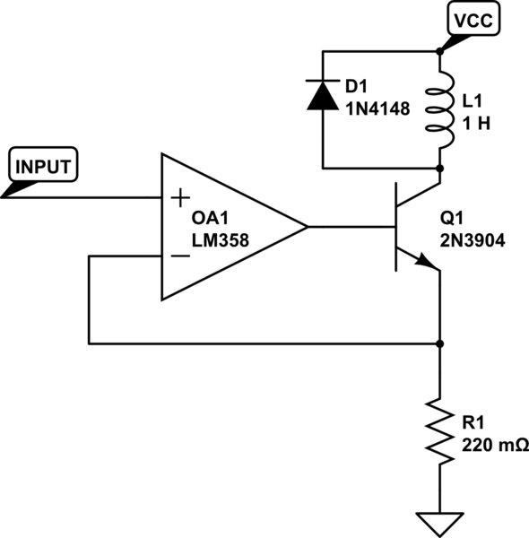
However, your circuit will change speed in which magnetic field change vill occur, but not the maximum magnetic flux. I would recommend you to check current controled coil instead of voltage controled, as with that you could limit the actual strength of a field. Sample circuit:

schematic

simulate this circuit – Schematic created using CircuitLab

\$\endgroup\$
11
  • \$\begingroup\$ Hmm... What do you mean by current controlled vs. voltage controlled? I'm using circuit I posted to achieve the result of variable velocity, so isn't that voltage control? And voltage is a result of current and vice versa anyway, so by changing voltage one changes current. I tried something like the circuit you posted with the solenoid on the transistor collector but could not get it to work. \$\endgroup\$
    – thegrinch
    Commented Aug 8, 2018 at 21:18
  • \$\begingroup\$ Also, it's a positive charge that builds up on the input to the coil, so having a diode to ground seems like it would be the useless one, since only negative current can flow through that diode. I thought by having a diode to VCC this positive charge could drain. Why isn't this the case? \$\endgroup\$
    – thegrinch
    Commented Aug 8, 2018 at 21:21
  • \$\begingroup\$ Also, I think it may actually be exactly that difference in speed with which the magnetic field changes that is producing variable velocities of firing. Which is the result I want, so that's a good thing, and not something I want to get rid of. \$\endgroup\$
    – thegrinch
    Commented Aug 8, 2018 at 21:24
  • \$\begingroup\$ 1) In coil, voltage is a derivative of current, and current is integral of voltage, constant current leads to 0 voltage and constant voltage > 0 leads to increasing current 2) There is no "charge buildup" in coil, there is a "current buildup", diode to the left does all the job. 3) Force is proportional to magnetic flux that is proportional to current, not voltage \$\endgroup\$
    – Sergio
    Commented Aug 8, 2018 at 23:09
  • \$\begingroup\$ 2) Still doesn't really answer my question, which is about polarity. Just corrects my terminology. The current that builds up is positive, not negative. I've seen this on a scope. So wouldn't that positive current need to drain to VCC, not GND? \$\endgroup\$
    – thegrinch
    Commented Aug 8, 2018 at 23:34

Your Answer

By clicking “Post Your Answer”, you agree to our terms of service and acknowledge you have read our privacy policy.

Not the answer you're looking for? Browse other questions tagged or ask your own question.