1
\$\begingroup\$

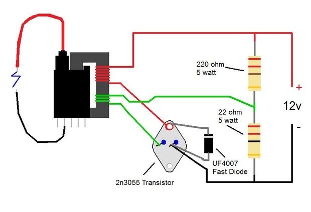
I am looking to assemble a power supply with an output of roughly 600 watts. One of the components required for such an apparatus is a 40 kVDC, 20 mA flyback transformer that I managed to find and hack in order to work for this specific purpose. I noticed that in this process, many people were calling for a transistor based circuit that seemed to be for transformer feedback. This was the circuit that I was considering:

enter image description here https://qph.fs.quoracdn.net/main-qimg-b6b61f0253f7c878d9e9a8507053aa42-c

Thus, I was first of all curious if such a circuit would be required for the flyback. If so, I was also curious if the shown parts and their descriptions would be capable of withstanding an input of 60 VDC and 10 A. Thank you.

\$\endgroup\$
3
  • \$\begingroup\$ How about 65kV boginjr.com/electronics/hv/flyback-driver-1 \$\endgroup\$
    – D.A.S.
    Commented Aug 9, 2018 at 1:42
  • \$\begingroup\$ @TonyEErocketscientist: perhaps I am wrong, but it seems to me that this “flyback” circuit is a BJT blocking oscillator in disguise. If it is not so, what are the differences? \$\endgroup\$ Commented Aug 9, 2018 at 7:09
  • \$\begingroup\$ The diode is in the wrong location. It is supposed to arrest the high voltage spike produced by THE COIL when the transistor turns off. Then it should be between the collector (anode) and the +12V (cathode). \$\endgroup\$
    – Audioguru
    Commented Jan 11, 2023 at 19:49

2 Answers 2

2
\$\begingroup\$

Look at the data sheet for the 2N3055 and note that the maximum power dissipation is ~115 W with an excellent heat sink, and that the maximum current rating is 15 A. 12 VDC at 15 A could theoretically produce 180 W out, but that would be for a "perfect" switching device with no dissipation. This circuit does not use the most efficient switching mode, so considerable power is wasted in heating the transistor.

That said, the circuit you show, apparently from Instructables, should work, actually producing a few thousand volts at a milliamp or two... far less than your suggested 600 W. This is a good thing, as one could get serious RF burns from a 600 W RF supply.

To get higher voltage, bypass the resistors with capacitors, as shown at PocketMagic. To get yet more voltage, the primary of the flyback transformer should resonate with the secondary, using an experimentally-determined capacitor.

If you make it, use a larger heat sink than that shown -- perhaps a heavy aluminum fry pan, with bottom filed flat. Use thermal compound, as well. In any case, the transistor will likely fail, particularly if you use more than 12 VDC. If it doesn't fry from overheating, high-voltage transients on the primary will likely destroy it. Still, this is a simple circuit, provides a learning opportunity, and is fun as long as it lasts.

More power can be output by this two-transistor push-pull circuit from RimStar, or the more complex one at Silicon Junction. The LM555 circuit could easily be made with frequency variable to determine if tuning affects spark length and current. BTW, a rough estimate of output voltage: between rounded conductors, ~1 kV/mm for the intial spark length.
\$\endgroup\$
2
  • 1
    \$\begingroup\$ Sorry if I seemed too negative (no pun intended). The circuit is worth trying but may not last long. Alternatives have been added. In your circuit, using Zeners across B-C and B-E will help prevent high-voltage damage. \$\endgroup\$ Commented Aug 9, 2018 at 2:19
  • \$\begingroup\$ Your local computer store probably often has 50-200W heat sinks on sale. Ones for older sockets falling into disuse can be quite cheap if you decide to go this way with things. \$\endgroup\$
    – K H
    Commented Aug 9, 2018 at 4:04
2
\$\begingroup\$

Some ideas...

600W is a lot. So some thoughts on how to manage that power.

A common technique with high-power drivers is to connect multiple drivers in parallel. You can do that with the 2n3055. This will reduce heating in each one.

Heatsinks that take multiple TO-3s are easy to find, either as new or salvaged from disused gear like linear power supplies (which may have the appropriate NPN’s on them even - bonus!)

Consider adding some kind of fuse though in case the transistor fails as a dead-short. A fan would be helpful too.

Might need another NPN connected Darlington-style to boost up gain.

Oh, and here’s a possibility - improved type of flyback driver using zero-voltage switching: https://www.instructables.com/id/ZVS-Driver/

\$\endgroup\$

Your Answer

By clicking “Post Your Answer”, you agree to our terms of service and acknowledge you have read our privacy policy.

Not the answer you're looking for? Browse other questions tagged or ask your own question.