9
\$\begingroup\$

For the longest time, I've stayed away from FETs and MOSFETs (when it comes to using discrete transistors in my circuits, that is). I'm taking a current hobby project as an excuse to try and finally get comfortable with using them. However, I can't seem to make heads or tails from these beasts.

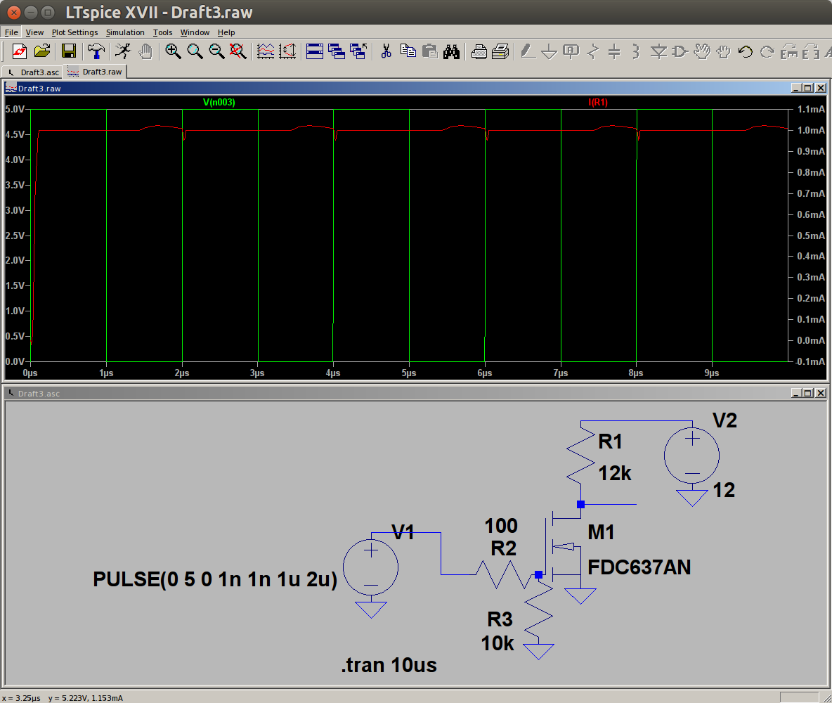
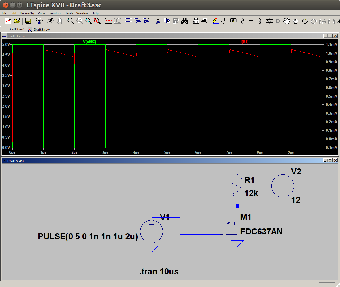
Before trying any real circuits, I'm running basic (almost "sanity check") LTspice simulations. Extremely simple circuits, and they still don't seem to work. For example, see this LTspice screen capture below — the voltage probe is at the output of the power supply; the current is measured through the resistor connected to the Drain pin. It is supposed to be 1mA when the MOSFET conducts (V2 is 12Volts), and I expect it to go back to 0mA for 1μs when the input voltage is 0V:

enter image description here

BTW, if I make V1 a DC source, then it works: I set it to 0V and the current through R1 is 0mA (well, in the order of pA), and if I set it to 5V, current is 1mA.

What am I missing? I also tried with a 100Ω resistor from V1 to the gate; it just makes a little round-ish bump in the current when switching, but it still does not come back to 0mA. I also added a 10k resistor from gate to GND. See image below, showing the output of the simulation (and again: what am I missing?):

enter image description here

I do have some more concrete questions on the topic, but I figure I better get comfortable with the simplest "toy" circuits before I try to do any "real" applications (even in the context of hobby projects).

\$\endgroup\$
2
  • 2
    \$\begingroup\$ Looks like you're switching your FET too quickly - try the first one again, this time with the gate voltage changing every second or so. \$\endgroup\$
    – Puffafish
    Commented Aug 13, 2018 at 14:53
  • \$\begingroup\$ Try a fast switching transistor like the 2N700x. \$\endgroup\$
    – CL.
    Commented Aug 13, 2018 at 14:59

1 Answer 1

14
\$\begingroup\$

Do the same simulation on a vastlty different time scale, like 1000 times slower. So change the us (micro seconds) to ms (milli seconds) and run the simulation again.

Note how in the first plot the red trace is going down but before it reaches zero you switch the NMOS on again. It has no time to reach zero !

There is a large capacitor present between gate and drain and combined with the 12 k drain resistor that is a large time constant. Larger than the 1us you're allowing it. So slow things down and see what happens.

When you get the curve you expect, lower the value of the drain resistor and note how the speed increases again. At 1 us you probably need 120 ohms or so, not 12 k ohm).

\$\endgroup\$
15
  • \$\begingroup\$ Ah. An answer beat my comment. Yes, gate capacitance will be the cause for the slow switching off of the FET. \$\endgroup\$
    – Puffafish
    Commented Aug 13, 2018 at 14:54
  • \$\begingroup\$ According to the manual of this part (fast switching N channel), worst turn-on/turn-off case is 42ns. Does that not take the internal capacitance in account? If not, where can you find the timing characteristics of the part? At 12V, the capacitance is roughly 1nF according to a table in the manual. \$\endgroup\$
    – Lundin
    Commented Aug 13, 2018 at 15:11
  • \$\begingroup\$ Aaahh — gate to drain capacitance!! In my mind, there was this "input capacitance" that I see in the specs, and I was picturing this one as gate to drain capacitance affecting only the input signal. It didn't occur to me to picture an "output capacitance" (so to speak). At any rate (no pun intended), it is working now! With the output resistor at 10Ω, it takes approx. 10ns for the output to swing. \$\endgroup\$
    – Cal-linux
    Commented Aug 13, 2018 at 15:27
  • \$\begingroup\$ As a meta-comment (if you indulge me) — funny how I seem to be very consistent with the mistakes/oversights/etc. I make .... Not long ago, I posted here a question on (somewhat)high frequency op-amps, and guess what: I was using my "default" resistor values (10k) that I'm used to for audio circuits, when in fact, for the bandwidth I was looking for, I needed resistors around 300Ω !!! Oh well, I'll choose to see consistency as a good thing :-) \$\endgroup\$
    – Cal-linux
    Commented Aug 13, 2018 at 15:31
  • \$\begingroup\$ I would also suggest looking closely at the turn on (at the gate) for the slower speed and seeing the gate plateau as the channel is pulled in. This is an inherent issue in enhancement mode MOSFETs, of course, but needs to be understood to get the most out of them. \$\endgroup\$ Commented Aug 13, 2018 at 15:46

Your Answer

By clicking “Post Your Answer”, you agree to our terms of service and acknowledge you have read our privacy policy.

Not the answer you're looking for? Browse other questions tagged or ask your own question.