1
\$\begingroup\$

I'm in need of a low offset opamp for integrating purposes, I also need it to be very low noise since the output of the opamp will go into a 3000 V/V gain stage.

The opamp that seems to satisfy my needs for low noise for the 3000V/V dual stage is: AD797 while the one that satisfies my low drift requirement is this: LTC1151

However when looking the datasheet of the LTC1151, I could'nt find the noise voltage spectral density, instead theres a volts peak to peak figure of \$ 1.5 \mu V_{p-p} \$ from 0.1 to 10Hz.

So my logic is that to get the noise voltage density I just need to divide by two (to get the peak voltage) and then divide by \$ \sqrt{10 Hz} \$, but im getting \$ 237.2 nV/\sqrt{Hz}\$ that seems too high. Is there something wrong with my calculations? Or is the voltage so high because its a zero drift op-amp? Im also aware that the 0.1 to 10 Hz voltage spec is mostly due to 1/f noise and not white noise of the opamp.

\$\endgroup\$
1
  • \$\begingroup\$ You should probably be comparing noise graphs AD797 fig 6 , and LT1151, page 5, 4th graph \$\endgroup\$
    – Henry Crun
    Commented Aug 21, 2018 at 22:51

2 Answers 2

1
\$\begingroup\$

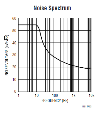
Usually it's in a graph, for 0 to 10Hz i'd go with rougly \$\frac{50nV}{\sqrt{Hz}}\$

enter image description here

\$\endgroup\$
4
  • 1
    \$\begingroup\$ That graph is for the integrator circuit shown not the device I expect. Real devices don't have noise flatten off below 10Hz, quite the opposite. \$\endgroup\$
    – Henry Crun
    Commented Aug 21, 2018 at 22:32
  • \$\begingroup\$ Hmm, actually probably a function of the chopper stabilisation of the chip. \$\endgroup\$
    – Henry Crun
    Commented Aug 21, 2018 at 22:47
  • \$\begingroup\$ Auto zero or zero drift amps usually have a noise profile that looks funny they modulate their 1/f noise to a different part of the spectrum \$\endgroup\$
    – Voltage Spike
    Commented Aug 22, 2018 at 4:24
  • \$\begingroup\$ yes obvious really, but I had never really seen/noticed/engaged-brain on that graph before. \$\endgroup\$
    – Henry Crun
    Commented Aug 22, 2018 at 4:33
1
\$\begingroup\$

Noise can only be specified knowing the particular input resistance.

BestNoiseR=NoiseV/NoiseI

At other resistances the noise figure will be worse.

Low voltage noise= low resistance, which somewhat conflicts with the desire for high input R to make an integrator.(separate preamp and integrator chips may be called for). You have to do some calculation to know what the lowest noise part will actually be in your circuit.

IC's are only low noise down to somewhere like ~200-500ohms, below that you need to use selected discrete bipolars for best performance.

Below the 1/f knee PSD becomes invalid as each 1Hz band has a different amount of noise in it - you need to integrate all the different values. Even then the non-gaussian nature of the noise (1/f^2 noise is a random walk) means that the relationship of pk-pk to rms does not hold true. This is why the tend to change to giving pk-pk values that make more useful sense than psd and rms.

You should probably be comparing noise graphs AD797 fig 6 , and LT1151, page 5, 4th graph

\$\endgroup\$
1
  • \$\begingroup\$ Step 1: borrow Art of Electronics, read low noise section. \$\endgroup\$
    – Henry Crun
    Commented Aug 21, 2018 at 23:39

Your Answer

By clicking “Post Your Answer”, you agree to our terms of service and acknowledge you have read our privacy policy.

Not the answer you're looking for? Browse other questions tagged or ask your own question.