2
\$\begingroup\$

Microchip is taking forever to activate my account so I will ask this here...

I am using the KSZ8081 PHY for MII Ethernet.

https://www.mouser.com/ProductDetail/Microchip-Technology-Micrel/KSZ8081MNXCA?qs=sGAEpiMZZMvdy8WAlGWLcC4eczfQr1zYEy39QIyqxLk%3d

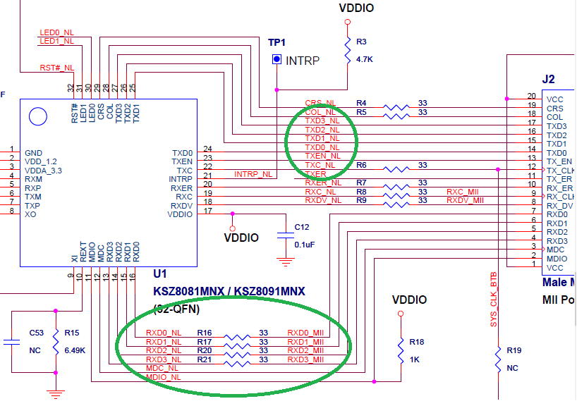
The evaluation board schematic has 33 Ohm impedance matching resistors on the RX MII signal lines but NOT the TX MII signal lines.

In past experience with other PHY chips (TI DP83848 specifically), there are series resistors on both the TX[0:3] and RX[0:3] lines.

Why does KSZ8081 not have them on the TX[0:3] MII lines? Would it be a good idea to include them or should I follow the evaluation board exactly?

Here is a screenshot of the KSZ8081 eval board schematic...

enter image description here

\$\endgroup\$

2 Answers 2

1
\$\begingroup\$

The RXD pins of the PHY are outputs. They may have fast edge rates. This, in combination with the signal path length from them to the MAC RXD pins, could easily result in transmission line effects (reflections and ringing) which the 33R series termination resistors are there to prevent.

You don't put series terminations at the receiver end of a unidirectional signal path. That's why they're not used for the TXD pins.

\$\endgroup\$
1
\$\begingroup\$

These aren't transmission lines so there is no characteristic impedance, and the lines run at either 25Mhz or 50Mhz depending on the speed of your RMII/MII interface, so it is advisable to insert a series resistor and this depends on the ports of the chips and their capacitance. It would probably be a good idea to follow the dev board. Try to keep the traces on one layer with a ground plane adjacent to it (the fast ones anyway) because any stray inductance and capacitance can reduce your rise times\speed.

The RMII signals are treated as lumped signals rather than transmission lines; no termination or controlled impedance is necessary; output drive (and thus slew rates) need to be as slow as possible (rise times from 1–5 ns) to permit this. Drivers should be able to drive 25 pF of capacitance which allows for PCB traces up to 0.30 m. At least the standard says the signals need not be treated as transmission lines. However, at 1 ns edge rates a trace longer than about 2.7 cm \${\textstyle {\big (}{\frac {1ns}{5.9{\frac{ns}{m}}}}\cdot {\frac {3.7m}{0.0254m}}\cdot {\frac{1}{6}}=4.115m{\big )}} \$, transmission line effects could be a significant problem; at 5 ns, traces can be 5 times longer. The IEEE version of the related MII standard specifies 68 Ω trace impedance. National recommends running 50 Ω traces with 33 Ω (adds to driver output impedance) series termination resistors for either MII or RMII mode to reduce reflections.[citation needed] National also suggests that traces be kept under 0.15 m long and matched within 0.05 m on length to minimize skew.

Source: Wikipedia Media Independent Interface

\$\endgroup\$

Your Answer

By clicking “Post Your Answer”, you agree to our terms of service and acknowledge you have read our privacy policy.

Not the answer you're looking for? Browse other questions tagged or ask your own question.