0
\$\begingroup\$

I was trying to power a transimpedance amplifier built with an op amp on a protoboard.

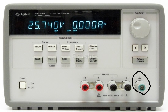
I only had a power supply that looked like the first image below (no COM, which I would have connected to GND of the op amp).

The answers I got for my initial question posted on this website were really good and perfectly explained what I was supposed to do. (I initially asked questions about different kinds of power supplies)

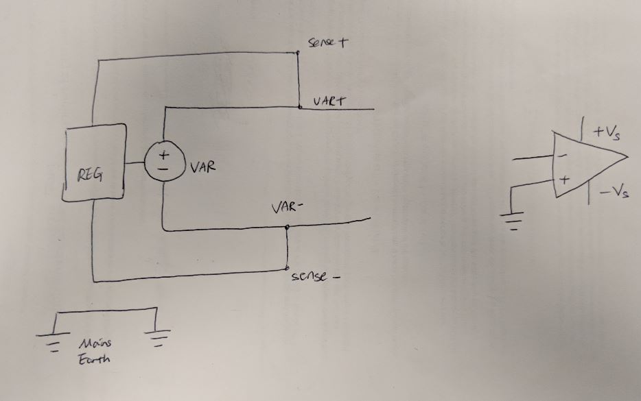
I made a mistake of connecting the mains earth of the power supply (circled in the first image below) to the + pin of the op-amp, where GND (COM of a power supply) was supposed to go. I understand why I was not supposed to do it. The mains earth is ill-defined since it is disconnected from both positive and negative voltage outputs of the power supply.

It seems I broke my op amp when I connected the mains earth to + pin of the op amp where GND (so COM) was supposed to go. I see that I was not supposed to do it.

My question is how did I break the op amp by connecting the mains earth to the + pin of the op amp?

enter image description here enter image description here

\$\endgroup\$
7
  • 1
    \$\begingroup\$ And your question is? \$\endgroup\$
    – Voltage Spike
    Commented Aug 25, 2018 at 18:24
  • \$\begingroup\$ What was IN- of the op-amp connected to? \$\endgroup\$
    – The Photon
    Commented Aug 25, 2018 at 18:25
  • \$\begingroup\$ That is a single supply. you will have to create a "virtual ground" midway between the supply terminals to act as a circuit ground for your op-amp circuit. You should not have any connection to the Mains Ground (the green post on the supply). \$\endgroup\$ Commented Aug 25, 2018 at 18:41
  • \$\begingroup\$ @laptop2d Thank you for the response. My question is how I broke the op-amp by connecting the mains earth to the + pin of the op amp. \$\endgroup\$
    – Blackwidow
    Commented Aug 25, 2018 at 18:48
  • \$\begingroup\$ @ThePhoton it was connected to some current from my other circuit, which I confirmed works and when I properly hooked up the op-amp with its + pin connected to COM of the power supply unit that has COM, everything worked well. \$\endgroup\$
    – Blackwidow
    Commented Aug 25, 2018 at 18:49

1 Answer 1

2
\$\begingroup\$

schematic

simulate this circuit – Schematic created using CircuitLab

Figure 1. What you've done.

enter image description here

Figure 2. What you're not accounting for.

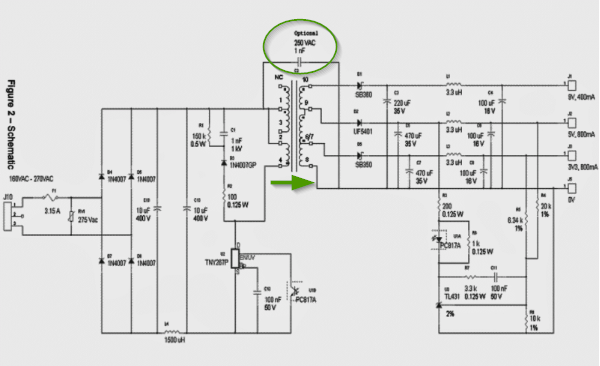
The power supply has capacitive coupling between the high-voltage side of the transformer and the low-voltage side. This occurs through the transformer capacitance and the deliberate capacitance circled in Figure 2. The effect of this is that the PSU output has a weak alternating voltage on it. You might be able to read this with a digital multimeter between one of the terminals and the mains earth.

schematic

simulate this circuit

Your op-amp has a very high input impedance and is very sensitive to over-voltage. Most likely is that the capacitively coupled voltage exceeded the maximum allowable input to the op-amp.

\$\endgroup\$

Your Answer

By clicking “Post Your Answer”, you agree to our terms of service and acknowledge you have read our privacy policy.

Not the answer you're looking for? Browse other questions tagged or ask your own question.