I'm using TI's 18-bit DAC9881 and need the output to go a little below 0Volts in order to account for offset voltages of following Op-Amp stages.
The DAC allows to provide a "low reference" between -0.2V and 0.2V to offset the output, which is just what I need.
My question is how to generate this reference voltage? It does not need to be very accurate (I need to calibrate the whole circuit anyway), but should be precise, i.e. stable over time. I have +5V/-5V LDO output power supply rails (TI LM27762).
One option would be to use a voltage divider connected to Op-Amp in voltage follower configuration. However, supply noise and load transients will disturb this poor man's reference.
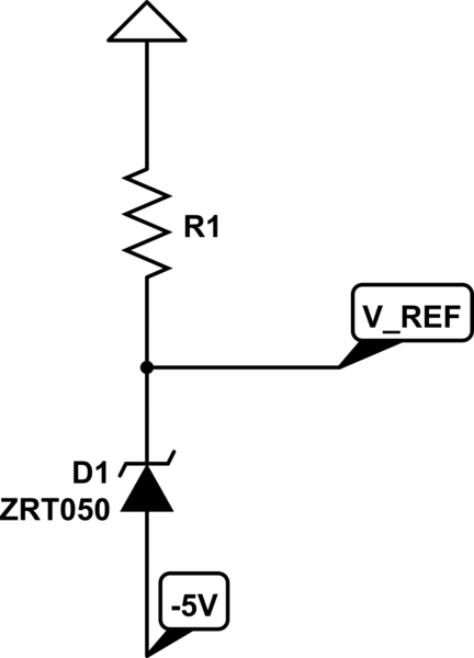
The other option I see is a shunt regulator. I didn't find any with a fixed reference voltage of 0.1V-0.2V, so the suggestion in this answer https://electronics.stackexchange.com/a/383440/197145 does not work. I did find a 4.9V reference (Diodes ZRT050) though, which could be used like this:

simulate this circuit – Schematic created using CircuitLab
However, this way (if it works?) the reference voltage is established with respect to the -5V power supply instead of GND, so I fear to get the same problems with noise and transients as with the op-amp solution.
Does anyone have a better option to implement a reference voltage of -0.1V to -0.2V from a 5V/-5V supply? If not, which of the two solutions seems more suitable and why?
Cheers, Kai
EDIT:
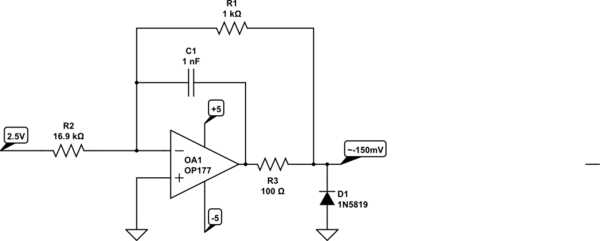
I built the circuit from the accepted answer and it provided the expected bias voltage. However, I read the datasheet of the DAC9881 wrong and found that my goal of shifting the output below GND by providing a negative bias voltage to the REFL input does not work. The amplifier in the output stage of the DAC has some fixed headroom to the negative supply (GND), which cannot be worked around by adding a negative offset. This can only be achieved with external circuity behind the DAC output.

