0
\$\begingroup\$

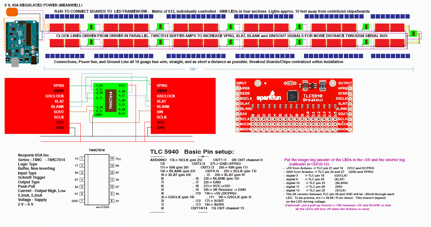
I am trying to send PWM, clock, latch and blank signals from Arduino through a series (16) of TLC5940 Breakout boards and on to a grid of 512 individual controlled LEDs six feet away (RJ45). I am using op-amps to help get the serial signals pushed through the large number of boards. Power and Ground are in parallel.

Of course, I am having problems. The set-up, as pictured, works well until the 9th or 10th board, then things get wonky. They are getting power but not individual control -just flickering.

I am trying to troubleshoot. The whole thing is powered by 12 V, 30 A switching power, buck converters for three different voltages (10 V for Arduino, 4.7 V for op-amps, 6V for boards and LEDs).

I am wondering if I should tie all grounds to a single common line back to the power source (V-) or do the individual voltages (10 V, 4.7 V, 6 V) need their own ground line back to power source? Example: the five op-amps - 4.7V+ and 12 V- single line common ground? - or should they have their own ground line all wired back to the 4.7 V converter and its 4.7 V-?

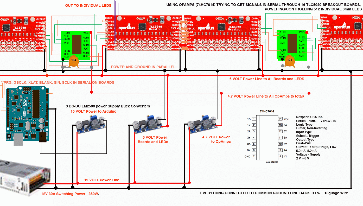
Power Diagram Full Diagram

\$\endgroup\$
3
  • \$\begingroup\$ Did you check the voltage over the last boards? Isn't it just voltage drop due to long wires? (leave them connected to same ground as shown on picture) \$\endgroup\$
    – Remco Vink
    Commented Aug 30, 2018 at 6:33
  • \$\begingroup\$ When I test the LAST (16th)board in the series, there seems to be near the same 6 V as the first (except I keep blowing out the first chip in the series:-) I was hoping that putting the Power and Ground in parallel would help that. They all power on after the ninth board, but with no individual control, just flicker. Unfortunately I can't or don't know how to test if the op-amps are working the signals past the first couple of them. \$\endgroup\$
    – adlib33e
    Commented Aug 30, 2018 at 6:45
  • \$\begingroup\$ Can you post a picture of the setup? Do you have an oscilloscope? Try using a lower SCLK clock frequency (change settings in arduino) see if it works better. What SCLK frequency are you using by the way? \$\endgroup\$
    – bobflux
    Commented Dec 23, 2019 at 2:04

5 Answers 5

1
\$\begingroup\$

There's nothing inherently wrong with using power line buses. Star wiring might not solve the problem.

Ideally, you'd use an oscilloscope to see how stable the power lines are. But I'll assume you don't have one.

Consider centre-feeding the power lines, rather than feeding the power in at one end. That reduces the cable runs.

Consider using fatter wires. The volt drop in a thin wire could be too high. Digital devices often require sudden spikes of current, so the power lines could be dipping even if the average voltage measured by a voltmeter looks good.

Consider adding capacitors - electrolytic and/or ceramic - between the power lines and ground near each board (you already seem to have a few ceramic ones on some boards only). This could end up a bit trial-and-error. Too little capacitance won't achieve what you want, too much will overload the power supplies on power-up causing them to shut down.

\$\endgroup\$
1
\$\begingroup\$

Just a word of warning - having multiple parallel ground lines designed for different currents is a recipe for disaster. If high-current power ground (e.g. LED) is accidentally disconnected all that current will go through (usually) thin wires for control supply. I've seen spectacular meltdowns of control boards connected by CAT5 for data and logic power and separate 10 AWG power lines.

From the picture in your question it seems you are using ubiquitous non-isolated Chinese DC-DC, which (again, usually) have common ground passing through. In this case it would be much safer to tie all supplies with just one ground wire to common bus.

\$\endgroup\$
0
\$\begingroup\$

Your DC-DC Modules have almost certainly an internal common Ground (Go ahead an measure resistivity). So you have them connected anyways. If you have problems the Power "Bus", as your diagram suggests, you should deploy a star configuration for your power, esp. ground.

\$\endgroup\$
0
\$\begingroup\$

Some points taken from old rules (about 1970 ;) ) of powering the large analogue/digital systems, containing large number of modules:

  1. Add 10...100uF capacitors (16 or 25V will be enough) on each PCB between it's each power pin and ground. You can remove existing 104 (=100nF) ceramic capacitors, shown on wiring diagram;

  2. Add 0.1uF (=104) ceramic capacitors between each power pins of each IC (as close to IC as possible) on each PCB;

  3. Use fatter wires - especially for ground and for powering LEDs (6V line). Wires taken from CAT5 network cable may be too thin for ground. Fatter wire is always better than thin ;)

So, these 10...100uF capacitors count should (has to) be equal to count of separated PCBs, and 0.1uF capacitors count should (has to) be equal to global count of ICs on all PCBs together.

Should help. These rules are something like "best practices of powering large systems". I'm using these rules on every system I made (regardless to the system scale: small or large), and I can confirm that they are always effective - it they are applied consistently.

\$\endgroup\$
2
  • 1
    \$\begingroup\$ 0.1 uF or 100 nF is "104" (1, 0, 0000 pF), "105" is 1 uF. \$\endgroup\$ Commented Dec 23, 2019 at 1:22
  • \$\begingroup\$ You are rigth of course ;) My mistake ;) \$\endgroup\$ Commented Dec 23, 2019 at 1:26
0
\$\begingroup\$

Warning: these cheapo "LM2596" are probably counterfeit.

Last time I tested one, it definitely wasn't a LM2596 (the frequency was wrong), inductor was saturating, output ripple voltage was terrible, and the input/output caps were extremely hot due to being "optimized" for cost rather than performance (ie, ESR way too high). These LM2596 modules are not going to last, the cheap "general purpose" caps are not designed for this kind of abuse, they are going to die and then the DC-DC may lose regulation and possibly destroy the rest of your setup. But before that happens, output ripple will become so bad that it will stop working anyway.

So if you need high current 6V you should really use a 6V power supply, these are not expensive. Considering the time you put into this it would really be a bummer if it failed due to counterfeit DC-DCs.

You can power the arduino from 6V using a LDO to output 5V, or use a cheap 5V USB phone charger.

You can also power your 74HC7014 from a 5V LDO or the same 5V supply as the arduino.

I am using op-amps to help get the serial signals pushed through the large number of boards. Power and Ground are in parallel.

Note: they are not opamps, they are logic gates, specifically buffers.

Since each package contains 6 buffers, make sure you connect the input of the unused ones to ground or they will pick up noise and switch randomly.

Note I didn't answer your question about grounding, the others did and I'd like to see a photo too. But you really need to get rid of the fake LM2596.

\$\endgroup\$

Your Answer

By clicking “Post Your Answer”, you agree to our terms of service and acknowledge you have read our privacy policy.

Not the answer you're looking for? Browse other questions tagged or ask your own question.