1
\$\begingroup\$

I am designing a device that takes in various types of industrial sensors.

Initially, I had a transmitter to take the PWM signal and convert it to 4mA-20mA.

After reading lots of articles about the subject, it is still unclear if these sensors use primarily PWM signals or output a value between 4mA-20mA.

\$\endgroup\$

2 Answers 2

3
\$\begingroup\$

Based on the sensors I've used, that really is how they work. They might use pwm internally, but the output is indeed a current signal.

If you only need to read the sensor, it can be done easily using a resistor like this: 4-20ma signal to voltage conversion circuit
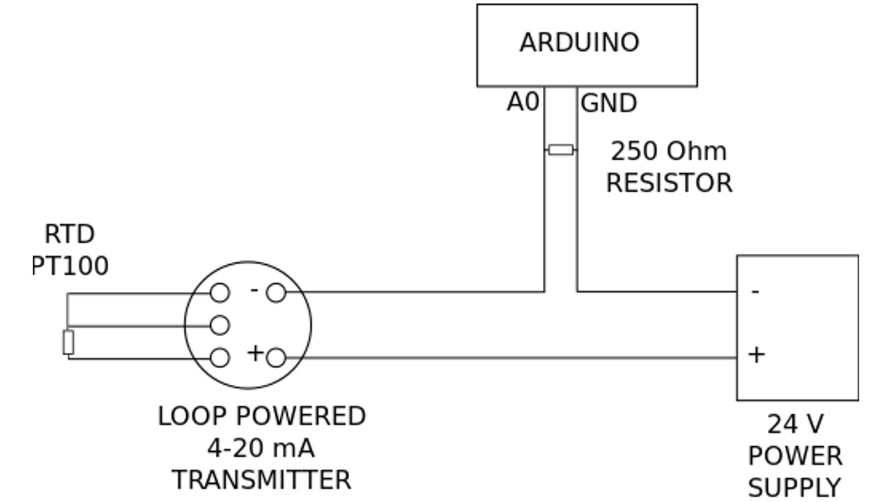
You can adjust the resistor value to adjust the peak voltage. 250R will give you 5v at 20ma.

Edit:

If you're trying to create a 4-20ma signal, your circuit is going to look something like this:
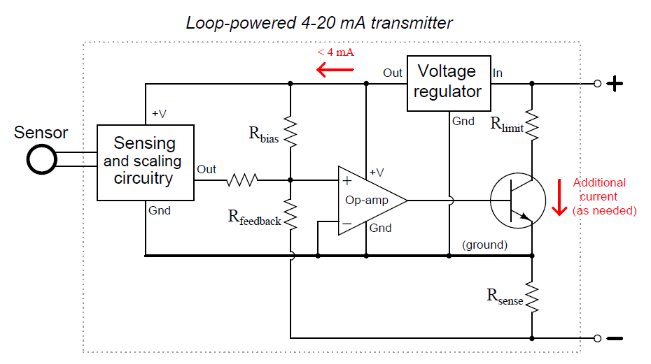
4-20ma signal generator circuit

As you can see it's not just pwm into a filter or something like that, which I get the impression is what you were thinking.

Edit2:

Upon re-reading your question it seems like maybe you're wondering what types of signals are most common? In my experience PWM is basically non-existent. 0-10v and 4-20ma are the most common signals. With flow meters you will sometimes also see high speed pulse signals, where 1 pulse corresponds to a fixed qty of flow.

\$\endgroup\$
3
  • \$\begingroup\$ So you arduino outputs an analog value that then goes into the transmitter? I'm confused by your graph. \$\endgroup\$
    – Roo
    Commented Sep 19, 2018 at 6:36
  • \$\begingroup\$ This circuit is for reading. A0 is a 0-5v analog input. Generating a 4-20ma signal is a whole other thing \$\endgroup\$
    – Drew
    Commented Sep 19, 2018 at 6:40
  • \$\begingroup\$ that circuit is missing any protection if the loop gets short-circuited. more than about 5.5V on A0 will damage the Arduino \$\endgroup\$ Commented Sep 19, 2018 at 7:23
0
\$\begingroup\$

4~20mA are analog current links immune to long cable resistance used by industrial sensors. These are low bandwidth so easily filtered, & converted.

But if power line noise is a major issue, shifting the spectrum up to some clock with PWM uses the bandwidth above the clock rate limited by the rise time and generally for short paths.

Others may choose a VCO to convert DC to f and back.

It all depends on the error tolerance, linearity, bandwidth, cable length and electromagnetic noise immunity needed.

\$\endgroup\$
2
  • \$\begingroup\$ Sorry Tony, your response doesn't help me figure this out. \$\endgroup\$
    – Roo
    Commented Sep 19, 2018 at 6:39
  • \$\begingroup\$ I wasn't clear what you did not understand..The 4~20 mA std.link is an analog loop, not digital PWM link and yes it is pretty standard for analog sensors on long industrial cables due to noise advantage. You can obviously loop up wiki to see more info \$\endgroup\$
    – D.A.S.
    Commented Sep 19, 2018 at 11:07

Your Answer

By clicking “Post Your Answer”, you agree to our terms of service and acknowledge you have read our privacy policy.

Not the answer you're looking for? Browse other questions tagged or ask your own question.