0
\$\begingroup\$

gerber-viewer-program

Eagle

Hello,

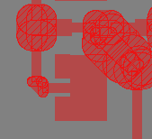
I want to import my microstrip patch antenna design from ADS into my Eagle-Board-View. Therefore I exported a Gerber-File, which looks good in the Gerber-Viewer. Inside Eagle, i used Gerber-Import-Function.

Unfortunately, it doesn't correctly represent certain parts of the design (e.g. curves), like it is shown above (1: what the gerber-viewer-program shows and how it should be; 2: eagle-screenshot)

Can anyone help me? I don't have any other useful File-Import-Option (a DXF-File is even worse importing), I tried to change different export-options for the Gerber-export in ADS but they don't change this problem.

\$\endgroup\$

1 Answer 1

1
\$\begingroup\$

I presume if you set the width of the polygons to 0, it will probably look correct. Granted that doesn't really help as setting width to 0 cannot be manufactured when exported from Eagle.

Gerber allows you to define apertures of any shape, and ADS can handle that properly, creating an aperture of the correct size and saying it should be filled.

The problem lies in the fact that Eagle is limited. Eagle cannot handle these aperture polygons correctly - it doesn't support proper filled shapes. Instead it uses a painting method to create fills (i.e. lots of traces zig-zagged back and fourth) - you can see this clearly when you set a layer display mode to hatched, there are lots of lines to fill the polygon. If you set the width to 0, it takes infinite lines to fill.


The only two approachs here that I know of to "hack" the correct results.

  1. Set the polygon width to some small non-zero value (beware, too small and your Eagle exported Gerber file becomes huge), and move the edges of the polygon in an amount equivalent to half the width.

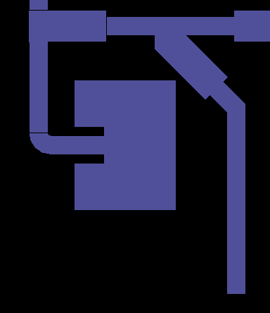
  2. The second is to trace over your design using rectangles and curved lines. If you set your imported polygon width to 0, this will give you the exact shape you want. You can then use a mixture of arcs of the correct width to form the curved sections, and rectangles to trace over flat areas. Remember that you can rotate rectangles in Eagle, so creating a box at 45 degrees is possible.

\$\endgroup\$
2
  • \$\begingroup\$ Thank you for this information. It looks more or less the same if I change polygon width but the file becomes bigger for lower values. I don't want to redraw all these traces. Maybe I should change the PCB-software tool? I have also KICAD but there is no Gerber-Import function. \$\endgroup\$
    – Daniel R.
    Commented Oct 11, 2018 at 23:58
  • \$\begingroup\$ @DanielR. perhaps. Having said that, there doesn't seem to be that many parts to your design that are polygons - four if I count correctly. Shouldn't take long to perform option 2. \$\endgroup\$ Commented Oct 12, 2018 at 0:15

Your Answer

By clicking “Post Your Answer”, you agree to our terms of service and acknowledge you have read our privacy policy.

Not the answer you're looking for? Browse other questions tagged or ask your own question.