6
\$\begingroup\$

I've recently obtained Sharp GP2Y0A21YK0F IR distance sensor and I'm not sure how to make a proper circuit for output measurement, since I'm getting lots of noise. The only thing datasheet mentions is that there should be a \$10 \mbox{ } \mu F\$ capacitor on power pins as close to sensor as possible. Well, I soldered it directly to the sensor's power pins and it didn't help.

Here's what the output looks on the scope:
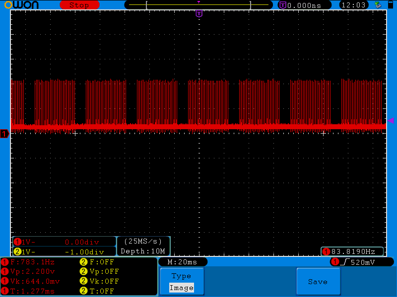
scope shot

The fat line at the bottom of the screen is the actual expected output and when I move my hand near the sensor, the line moves as expected, but the peaks remain the same.

Using an LC filter did remove the peaks, but I'd like to know if there's some industry standard way of solving the problem I have.

\$\endgroup\$
2
  • 1
    \$\begingroup\$ Can you post your circuit? What else is in this system? How is it powered? Are these same spikes present on the input power to the sensor? \$\endgroup\$
    – Ryan
    Commented Sep 13, 2012 at 12:35
  • \$\begingroup\$ @Ryan There is nothing else in the system. Only the sensor, power supply, scope and maybe 40 cm of cables. I don't see any spikes on the power connector of the sensor. There's around 50 mV peak to peak of ripple, but I don't see why that would be a problem. \$\endgroup\$
    – AndrejaKo
    Commented Sep 13, 2012 at 13:31

2 Answers 2

4
\$\begingroup\$

These sensors really put a lot of noise on the line. I'm using here a similar sensor (the GP2D120XJ00F). First, add another 100nF ceramic cap parallel to the existing 10µF cap. This helps to better damp the changes in current consumption of this sensor. Additionally, I added a low-pass filter to the output (10k resistor and 100nF capacitor), to smooth the output signal. (I then use an averaging filter in the MCU when reading the input, but then I don't have the need for really fast reaction times).

\$\endgroup\$
5
  • \$\begingroup\$ The 100 nF capacitor definitely improved the output. It's still not very clean, but it's much better now. Thanks a lot! \$\endgroup\$
    – AndrejaKo
    Commented Sep 13, 2012 at 21:25
  • \$\begingroup\$ Which one? The 100nF for the supply, or the low-pass filter on the output? \$\endgroup\$
    – hli
    Commented Sep 14, 2012 at 6:42
  • \$\begingroup\$ I also found some other guy having problems with the sensor messing with the power supply quality - maybe this will help you too. And if you look at this page entry, you will see that the power consumption spikes correspond with your problematic readings - so it could just be that the power supply noise is coupled into your output wire. (The coupling can also be via the ground wire - does the oscilloscope probe share the ground line with the power supply, or is its ground line connected directly to the sensor?) \$\endgroup\$
    – hli
    Commented Sep 14, 2012 at 6:50
  • \$\begingroup\$ The capacitor on the power supply helped a lot. I still haven't tried with the filter on the output mainly because my junkbox needs refilling. The scope probe's ground is connected to the point where the PSU cable is connected to the cable going into the sensor. \$\endgroup\$
    – AndrejaKo
    Commented Sep 14, 2012 at 7:44
  • \$\begingroup\$ So this scope connection means that scope and power share a common path. And then all changes in current consumption for the sensor lead to voltage drops on this path, which changes the output signal. That's why adding these capacitors help. \$\endgroup\$
    – hli
    Commented Sep 14, 2012 at 13:01
2
\$\begingroup\$

Your problem maybe because of 60 Hz power noise. It comes from light bulb. Using 60 hz noise filter is invertible. So, use high frequency for sending data and first some high pass filter for removing this noise and at last a low pass filter to improve signal could help you. I had same project and use this solution.

\$\endgroup\$
2
  • \$\begingroup\$ +1 for the effort, but in this case, that doesn't appear to be the problem. Even in the dark, I still get the spikes. Also wouldn't that produce continuous disturbances? I have 9 to 10 ms pauses between groups of peaks. Also wouldn't the peaks be synchronized to power line frequency if that was the problem? Mine aren't. \$\endgroup\$
    – AndrejaKo
    Commented Sep 13, 2012 at 20:14
  • \$\begingroup\$ You are right. But i had many problem with this noise, it maybe come from another source. Have you seen spectrum of your signal? and what is your noise period? Please expand oscilloscope period time and determine your noise period. Then it will be simple for attenuate it. \$\endgroup\$
    – mehdi
    Commented Sep 14, 2012 at 12:17

Your Answer

By clicking “Post Your Answer”, you agree to our terms of service and acknowledge you have read our privacy policy.

Not the answer you're looking for? Browse other questions tagged or ask your own question.