2
\$\begingroup\$

We use a buck converter to drive a resistive load with varying voltage/power. Now we detected a problem with load disconnection at high duty cycles where the driving mosfets and the flyback diode burn and the buck converter gets shorted entirely. I made a simplified simulation of our circuit to demonstrate the problem, the switch S1 simulates load disconnection after 5ms: buck converter load disconnection
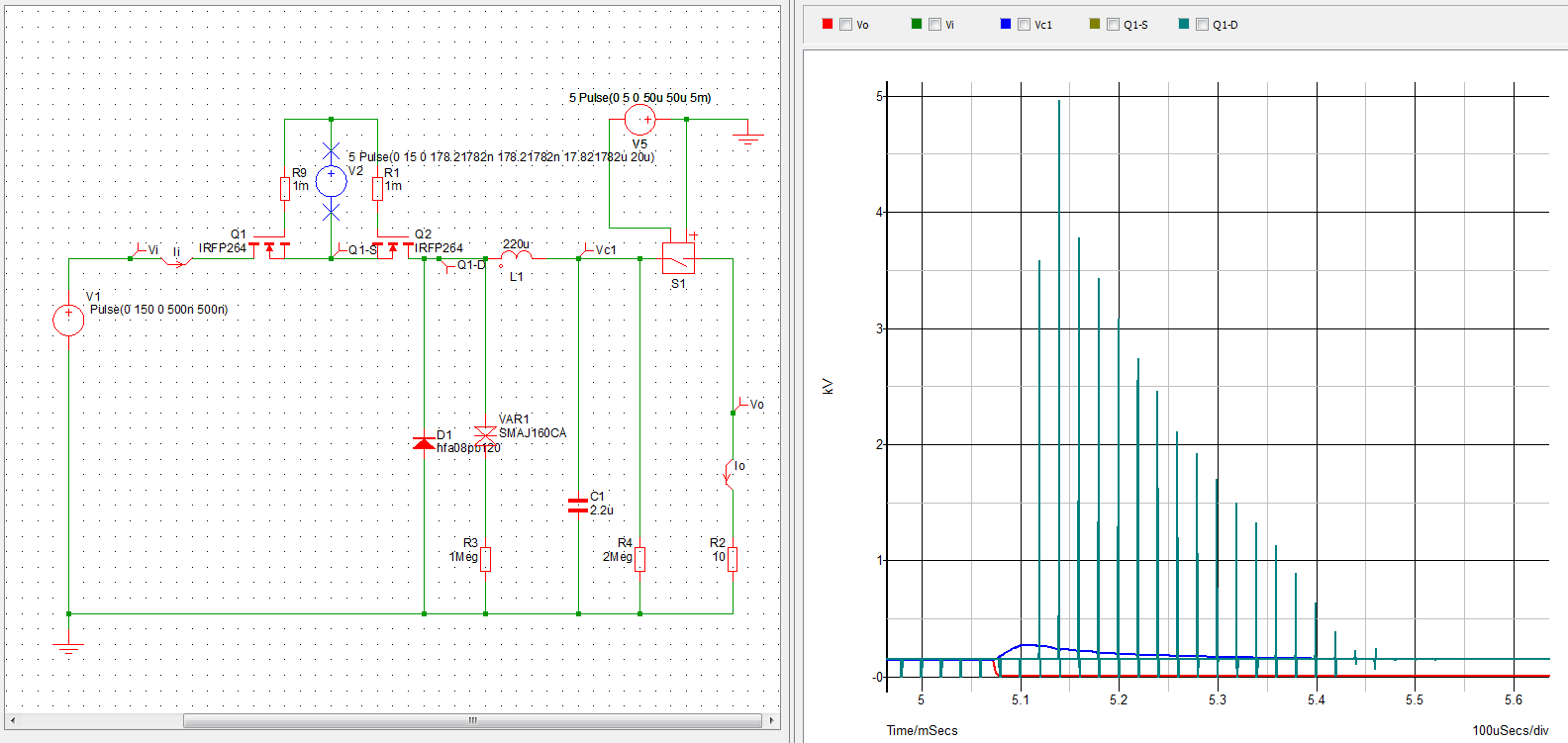
Here switching frequency is 50kHz and duty cycle is 90% and very high voltage spikes occur. When the duty cycle drops below ca 60% the overvoltage spikes do not show up anymore.

I know already from Buck converters- No Load condition that a synchronous buck converter would not have this problem and I've already simulated this and can confirm this. But synchronous buck converter cannot be used here anymore, we need to quickly fix this present solution.

The schematic shows some solutions we've tried:

  1. Putting a high voltage TVS diode (VAR1), i.e. changing R3 to e.g. 1mOhm. This helps a bit but still we get spikes over 800V which would damage the components. Adding a TVS (transil)
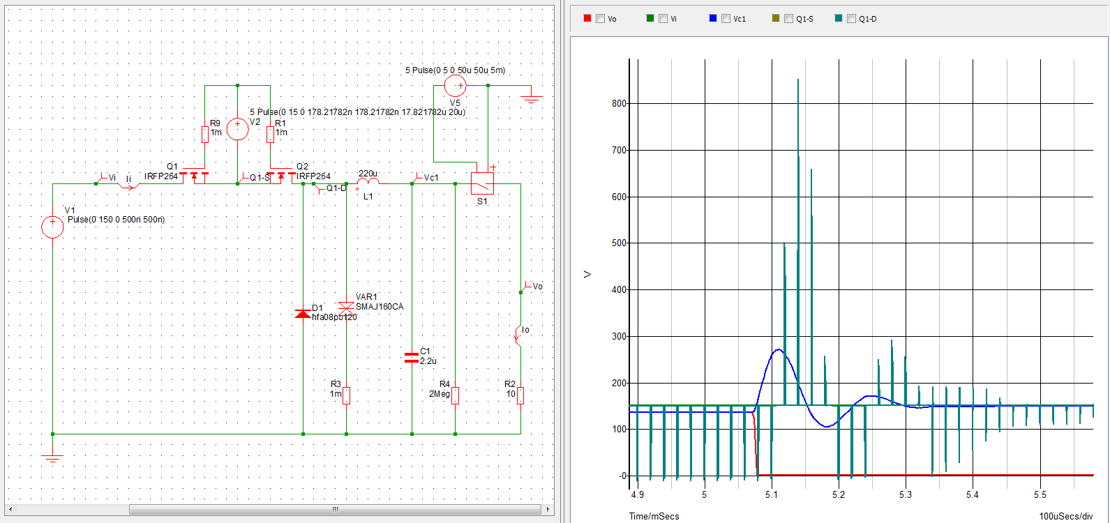
  2. Adding a bypass (bleeder) resistor R4. But this does not help either until it is set below ca 20 Ohm, which is of course unusable in real application.

Of course in real application the load current is measured and when there is underload or overload the mosfet driving gets disconnected (not simulated here). But this takes at least 20 ms and cannot be made shorter. Here the damage happens within max 100 us from the point the load gets disconnected.

The question is of course, how to avoid this damage with minimum effort, cheap, low part count, space saving etc.

Simulation file in Simetrix Elements 8.1 (free evaluation)

\$\endgroup\$
3
  • \$\begingroup\$ Is your inductor saturating? \$\endgroup\$ Commented Oct 24, 2018 at 16:56
  • \$\begingroup\$ What Vout, what Iout? Show waveforms, using a very short ground-lead to the scope probe (0.5" gnd). Show the PCB layout. \$\endgroup\$ Commented Oct 24, 2018 at 17:06
  • \$\begingroup\$ @analogsystemsrf: Please only refer to the simulation which demonstrates the problem, not the real schematic or PCB which is not shown here and cannot be. Waveforms shown. Vout is shown in red, Iout should be clear then. \$\endgroup\$
    – tk_
    Commented Oct 24, 2018 at 18:30

2 Answers 2

1
\$\begingroup\$

You could provide a RC snubber circuit parallel to the diode (google for “RC snubber DCDC”) This slows down the sharp edges of the switching waveform and of course reduces efficiency a bit. This is often done to reduce EMI problems, and it might also help reducing the harmful voltage spikes.

\$\endgroup\$
2
  • \$\begingroup\$ I've simulated this. RC snubber helps a lot (suitable values here R=10Ohm,C=220-330n] \$\endgroup\$
    – tk_
    Commented Oct 25, 2018 at 17:14
  • \$\begingroup\$ RC snubber helps a lot thank you. Simulated this, R=10Ohm,C=220-330nF appear to be best values. However snubber does not help such a way we need. It chops the spikes to be ca 2x Vi, here 300V. But we need 200V max. I think we have to test different TVS in real application to find a solution. TVS diode should chop the spikes. I don't know why in the simulation it is not done. This should be the first comment but I pressed some key accidentally that confirmed the first comment but somehow it was not shown until now... \$\endgroup\$
    – tk_
    Commented Oct 25, 2018 at 17:20
1
\$\begingroup\$

It seems, at least for the presented simulation, that the solution with TVS diode is the only sufficiently working solution.

But other type of TVS diode has to be used.

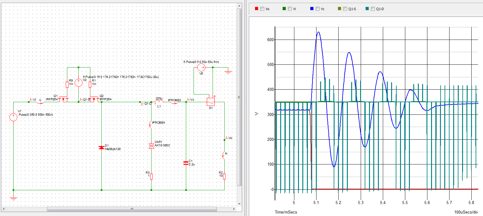
SMAJ types are not suitable for clamping such high currents, again only when simulated with model files downloaded from Littelfuse model library. For used SMAJ160CA the current flowing through it exceeds its Ipp more than 5 times.

When I use the AK10 type, again simulated with model file from Littelfuse, the clamping works as expected: enter image description here

Now we have to buy samples of those TVS diodes and check them in real application.

Because this question was only about simulation this answer can be IMO accepted.

\$\endgroup\$

Your Answer

By clicking “Post Your Answer”, you agree to our terms of service and acknowledge you have read our privacy policy.

Not the answer you're looking for? Browse other questions tagged or ask your own question.