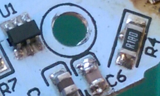
UPDATE TWO
I have included a picture with some updated readings
Forget about the resistor.
This board has a constant current driver.
U1 is the driver chip.
If you can read the part number of U1 that would help confirm my answer.
What is needed from the datasheet is the Rsense reference voltage.
I suspect R4 (marked R180) is the current sense resistor with a value of 0.18 Ω.

There are not many high current LED driver chips in a 6 pin package.
Very likely the circuit below is similar to this one.
Rs would be your R4.
All the current flowing through the LED flows through R4.
The driver chip measures the voltage across R4 to know whether to increase or decrease the current.
The internal reference voltage is compared to the voltage between Vin and the SENSE pin.
If the measured voltage is lower than the reference voltage the current is increased until the voltage match (and vice versa if higher).

Replace all the components back to their original values.
Measure the voltage across R4.
The R4 voltage divided by 0.18 is the LED current.
The current will change linearly with changes in the value of R4.
The LED is a very high power LED. Likely a max current of 2A or more.
It appears to have 6 dice.
The arrows point to the spaces between the dice.

This is high lumen density LED used for stadium lighting and street lights. Probably between 1000 and 2000 lumens at 1 Amp. The forward voltage is likely to be 9V or 11-12V. Just measure the voltage across the + and - terminals of the LED, if you want to know, but it does not matter.
To increase the current, lower the value of R4.
EXAMPLE:
Let's say the reference voltage is 0.15V.
The current would be 0.15 ÷ R
0.15 / 1.8Ω = 833 mA
Given the above criteria, if you wanted to increase to 1 A.
The resistor value would be 0.15 Ω (0.15V/ 1 A)
R6 and R7
R6 and R6 may be a voltage divider to apply an external voltage to the ADJ pin. This could be used to fine tune the current to a lower current set by R4. R4 sets the maximum current and a voltage applied to ADJ can reduce the LED current from that set by R4.
R4 could also fix the switching frequency as well as the max current. Then the voltage on the ADJ pin would create an internal PWM signal to reduce the LED current.
END OF UPDATE TWO
UPDATE ONE
Using a 47Ω results in the LED being dimmer than it would be on an
unmodified circuit board (I have an identical light which I can use
for comparisons). 100Ω and above do not burn out at all. Also, to
clarify, the LED is normally white, not blue, and I understand the
colour change to blue is because of excess current.
White LEDs are often a blue LED with phosphor wavelength converters to convert the blue to white. Both blue and white are about 3V. It sounds like you have a high power white LED where a safe current would be about 350 mA.
Is it correct to assume the 22 Ω resistor gave you sufficient brightness?
For safety sake let's assume the supply is 12V rather than 7V.
For 350 mA at 12V you will need a 6W 25Ω resistor.
For 350 mA at 7V you will need a 3W 11Ω resistor.
What is the purpose of the LED?
Does it look like this (3 mm x 3 mm)?

Or this?

Post a picture of the LED.
END OF UPDATE
I measured the voltage from the pin to ground at 7V
the LED turns blue and dims
the power source is 11-12V
I am assuming the forward voltage of the LED is about 3V based on the blue.
If it's 7V supply to the LED and resistor, try a 200 Ω resistor.
200 Ω will give you 20 mA and 80 mW for the resistor, which is a very safe place to start.
If 200 Ω is too dim try 100 Ω
If 200 Ω gets too hot, try 500 Ω (supply voltage may be higher than 7V)
The 500 Ω would give you about 20 mA if the supply voltage is 12V.
What you did not say about the 47 Ω was how bright was the LED.
If the supply voltage is 7V 47 Ω would give you about 80 mA and 325 mW from the resistor.
A 22Ω would give you about 180 mA and 720 mW from the resistor with a 7V supply.
A 22Ω would give you about 400 mA and 3600 mW from the resistor with a 12V supply.
how should I correctly measure the amperage without putting across a
voltage source?
You measure the voltage across the resistor then divided the voltage by the resistor value. If 5V across a 47 Ω resistor the current is 106 mA (5V/47Ω).
The voltage across the resistor will give you the supply voltage too.
If the resistor voltage is about 5V then the supply is about 7V.
If the resistor voltage is about 9 then the supply is about 12V.


