0
\$\begingroup\$

I want to simulate a simplistic "Van der Pol oscillator" in a circuit simulator such as LTspice or circuitLab.

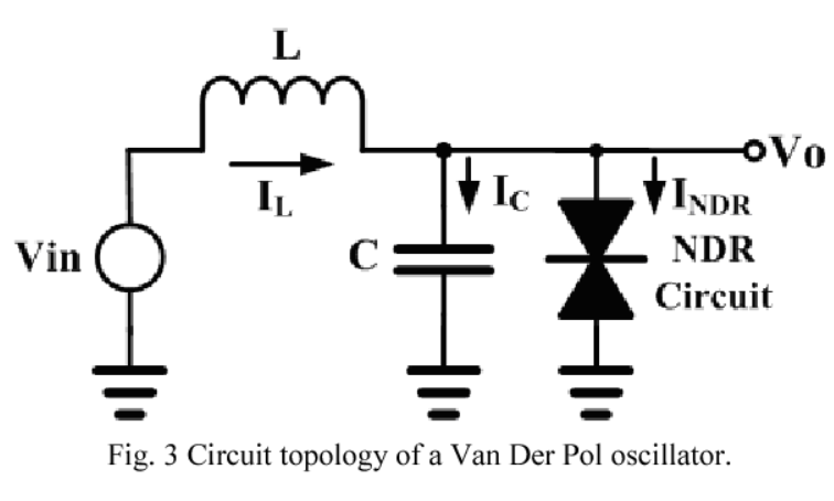
The only circuit I found is the following:

enter image description here

But this requires negative resistance implementation which I don't know. I couldn't find any whole implementation for such oscillator with its component values.

I would appreciate any help who are into the subject.

Edit:

Here I have combined pieces from net and here. So the below might be wrong:

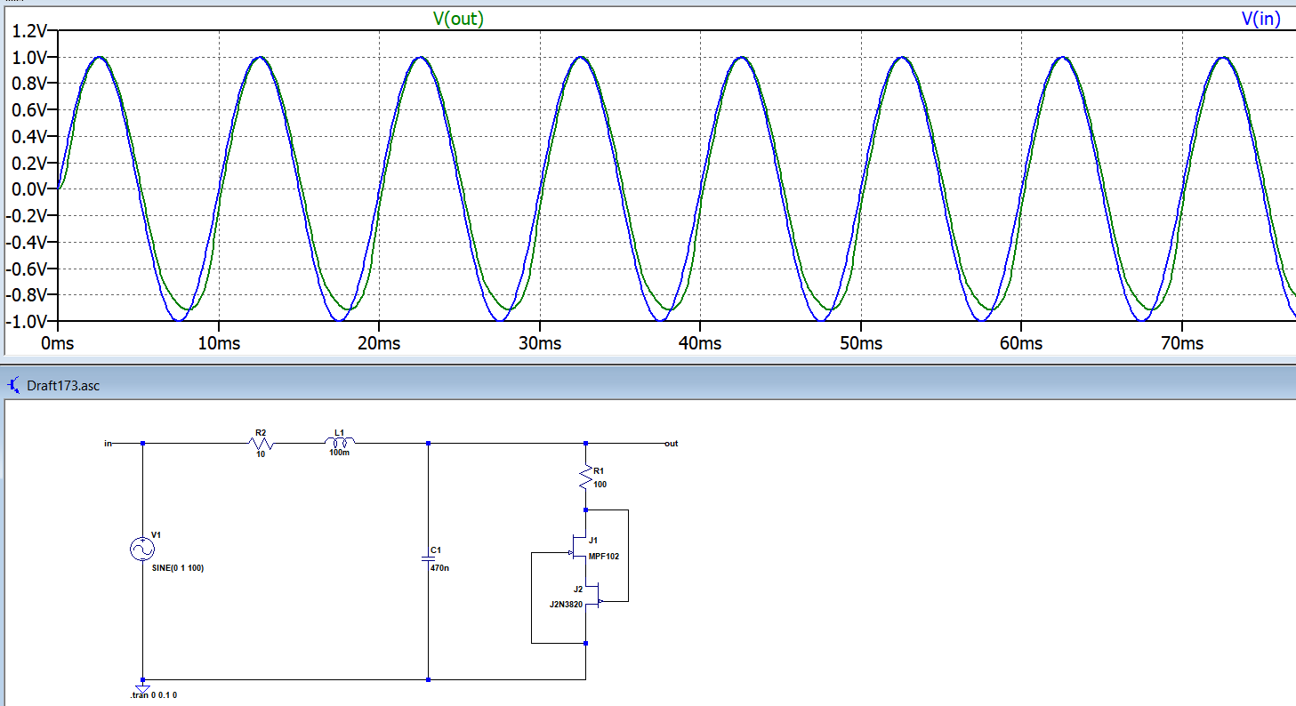
100Hz Sine input amplitude 1V:

enter image description here

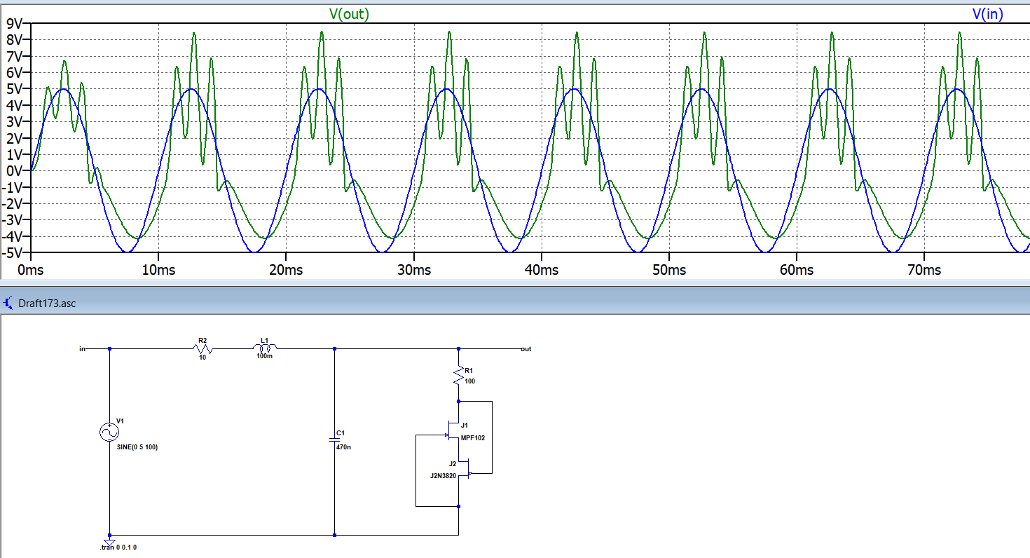
100Hz Sine input amplitude 5V:

enter image description here

Can someone explain what is going on? Is that what this oscillator supposed to output?

I'm especially trying to see non linear and chaotic behavior.

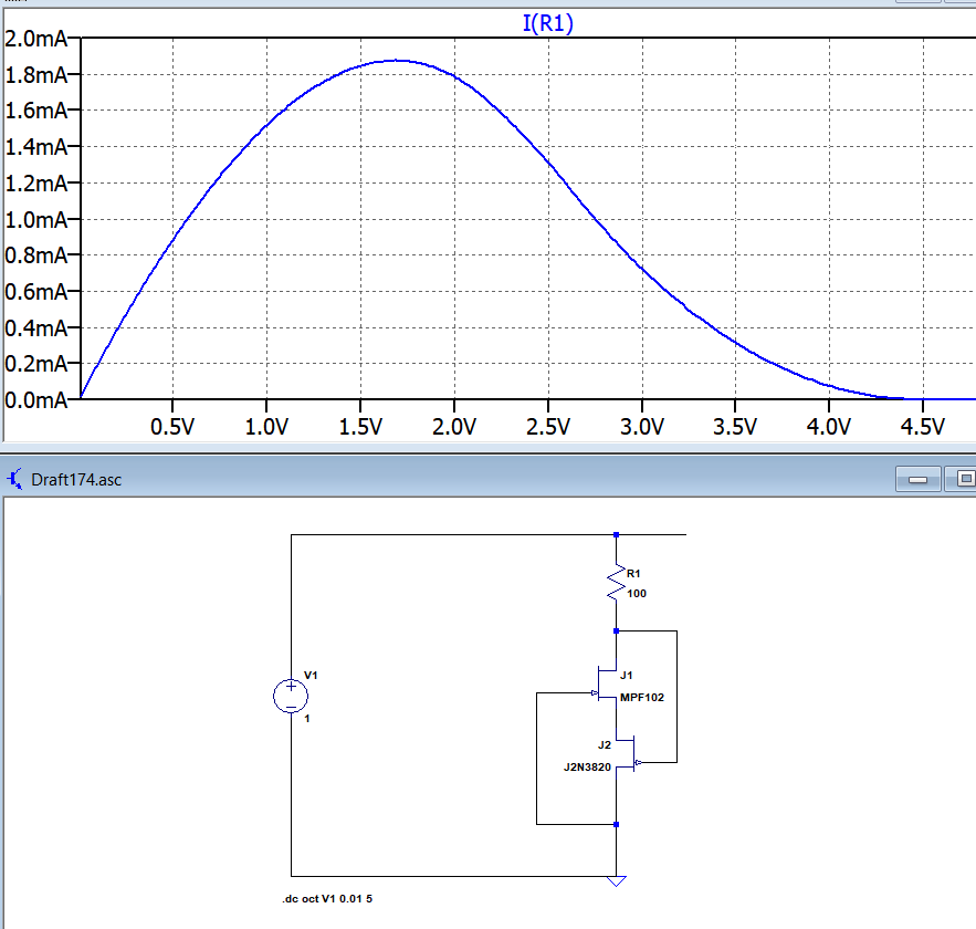
It seems one needs to be sure about the current region to operate as a negative resistance:

enter image description here

\$\endgroup\$
7
  • \$\begingroup\$ "this requires a negative resistance implementation": huh, how so? There's definitely no negative resistance in your circuit (but your semiconductor device might have operating points where more voltage means less current) \$\endgroup\$ Commented Oct 31, 2018 at 12:51
  • \$\begingroup\$ Most simulators will happily produce the right result if you enter a value of resistance that is negative. \$\endgroup\$
    – Andy aka
    Commented Oct 31, 2018 at 12:51
  • \$\begingroup\$ @Andyaka here they use tunnel diode for negative resistance www-m2.ma.tum.de/bin/view/Allgemeines/SGMVDP I need the actual circuit to implement. I couldnt find a finished example with values or exact components. \$\endgroup\$
    – user16307
    Commented Oct 31, 2018 at 12:54
  • \$\begingroup\$ What you need is a proper model for a tunnel diode. It will be a challenge to find one I think. You could also make your own model, that's not so easy, to get an idea, read here: hindawi.com/journals/apec/2011/830182 and pdfs.semanticscholar.org/7b2a/… \$\endgroup\$ Commented Oct 31, 2018 at 13:08
  • \$\begingroup\$ I know that the falstad circuit simulator has a model for a tunnel diode. It might also be possible to use a lambda diode, which is a simple configuration of two jfets that exhibits negative differential resistance. \$\endgroup\$
    – Hearth
    Commented Oct 31, 2018 at 13:13

2 Answers 2

1
\$\begingroup\$

Can someone explain what is going on?

In your top schematic, you're exciting the circuit with a sinusoid, and it's just following along, presumably because you're not giving the oscillator section enough supply voltage to do anything.

In the bottom circuit, you see oscillation happening at the peaks of the input sine wave, but not at the valleys. Presumably this means that if you just gave it a straight +5V it would oscillate. If the JFETs were perfectly matched I would expect it to oscillate at the valleys of the sine wave, too.

Is that what this oscillator supposed to output?

I doubt it. Usually you want to feed an oscillator a DC voltage and have it give you a periodic output. You're giving it a sinusoid where it's DC power would usually be applied.

I'm especially trying to see non linear

Well, you're seeing it! When your supply voltage is below about 3V or so, the oscillator's not starting up. Then it gets up above 3V and it oscillates until it drops back down again. Replace your sinusoid with a DC voltage, diddle with the value until you see oscillation, and you will, by definition, be seeing nonlinear behavior.

and chaotic behavior.

Oi. First, if the intent of whatever article you're going off of was to feed the oscillator with DC, you're most likely not going to get chaotic behavior from that circuit. There's a principle in nonlinear system that in order to see chaotic behavior you either need three energy storage devices (i.e., inductors and capacitors), or you need two energy storage devices and a forced time-varying input.

Your circuit as shown does satisfy the latter condition, so you may be able to find one or more families of operating points that gives you chaotic behavior. I would expect that for input frequencies close to the higher sub-harmonics of the natural oscillation frequency the oscillator will "lock in" to a harmonic of the input frequency and the output will be boring. For very low input frequencies the behavior will be technically chaotic, but not strikingly so. Somewhere in between (at appropriate input amplitudes and bias) you will find joy.

To look for chaotic behavior, set up a graph of inductor current against capacitor voltage. Technically this is the state-space trajectory of the system. Now look for a trace that seems to be orbiting a strange attractor. Now vary the input frequency, amplitude, and bias, and see how the character of the trace varies. If you're doing it experimentally you'd need to vary the input amplitude, frequency, and maybe the bias, and see if you find joy.

If you want a simple, realizable electronic circuit that exhibits autonomous chaotic behavior (i.e., that doesn't need to be driven by a sine wave) do a web search on Chua's Circuit. I believe there are single-transistor implementations* of it, but it's easier to do an op-amp implementation. There should be projects on the web -- if not, check back here.

* I remember building one by accident in my undergrad years and recognizing it's behavior as chaotic, but it was when chaos in circuits was only just being recognized as a thing, and my school did not feature profs who stayed au courant, so it remained my personal curiosity.

\$\endgroup\$
1
  • \$\begingroup\$ I'm a bit unclear on what your ultimate goal is. You're building a circuit, that you just seem interested in simulating, but then you express interest in mechanical systems with similar behavior. If you're just going to do things in simulation anyway, why not get a student copy of Matlab or a copy of Scilab and simulate a Van der Pol oscillator at the block diagram level? Or write out the dynamics of the actual mechanical systems you seem to actually be interested in, and simulate them? \$\endgroup\$
    – TimWescott
    Commented Oct 31, 2018 at 16:46
0
\$\begingroup\$

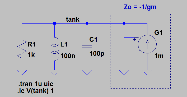
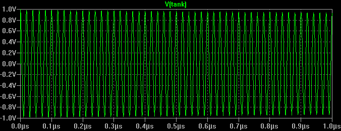
Here is a starting point for a basic LC tank oscillator:

enter image description here

Since the active gain element provides a negative resistance equal in magnitude to \$R_1\$, tank resonance is maintained at a constant amplitude.

enter image description here

\$\endgroup\$
2
  • \$\begingroup\$ Van der Pol oscillator? \$\endgroup\$
    – LvW
    Commented Oct 31, 2018 at 14:01
  • \$\begingroup\$ @LvW It's a starting point for OP. GM amp can be replaced with behavioral current source for non-linear response. \$\endgroup\$
    – sstobbe
    Commented Oct 31, 2018 at 14:34

Your Answer

By clicking “Post Your Answer”, you agree to our terms of service and acknowledge you have read our privacy policy.

Not the answer you're looking for? Browse other questions tagged or ask your own question.