1
\$\begingroup\$

So I have been given a circuit which supposedly works. The circuit was the the one shown but with a 10k resistor where the scribbles are. enter image description here Q17 is an IRLM6344TRPbF N-chanel MOSFET and Q16 is a ZXMP6A17G P-channel MOSFET
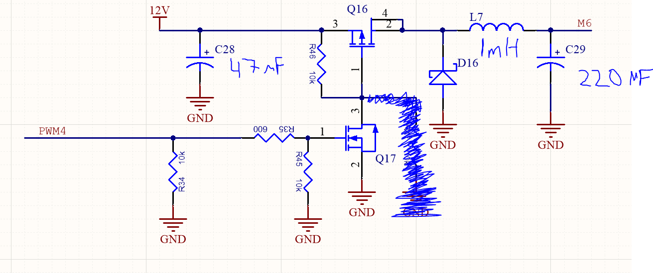
This didn't work at first until I removed the scribbled out resistor. After I managed to get it to actually change the output voltage dependant on the PWM signal that is applied, I encountered a weird problem.

The problem was that there was a weird correlation between the PWM duty cycle and the output voltage. When the duty cycle is between 0-30% the output voltage is ranging from 0-11 V and then increasing the duty cycle from 30% to 100% slightly increases the voltage until an output voltage of 11.8 V is achieved.

Can anyone explain why that is the case or what I am misunderstanding/doing wrong?

\$\endgroup\$
8
  • 1
    \$\begingroup\$ When you measure your voltage, is there any load (motor, resistor...) ? If not, you are certainly in discontinuous conduction mode, and the voltage is no longer proportional to the duty cycle. See fig. 5.11 on this link \$\endgroup\$ Commented Nov 2, 2018 at 10:14
  • \$\begingroup\$ @CharlesJOUBERT Yes I have the Brushless motor connected as the load \$\endgroup\$
    – muda
    Commented Nov 2, 2018 at 10:28
  • 1
    \$\begingroup\$ Ok. But depending on several parameters (current in the motor, PWM frequency, inductance...) you still can be in discontinuous conduction mode for a part of your duty cycle range. And then you don't have a linear relationship. Do you have an oscilloscope ? If so, you could measure the voltage across D16, this could give the answer. See also Bimpelrekkie answer. \$\endgroup\$ Commented Nov 2, 2018 at 10:35
  • \$\begingroup\$ I have already checked the voltage across the D16, that part of the circuit just smoothens the output from the P-channel MOSFET (which is a DC voltage). I guess this weird behaviour could be due to the internal circuitry of the motor and I could just account for it in my control system. \$\endgroup\$
    – muda
    Commented Nov 2, 2018 at 10:39
  • \$\begingroup\$ Who gave you the "circuit" ? \$\endgroup\$
    – Autistic
    Commented Nov 2, 2018 at 10:44

1 Answer 1

1
\$\begingroup\$

You cannot and should not expect a one to one relation between the PWM duty cycle and the output voltage. The actual output voltage strongly depends on the load.

I guess that your load is the brushless motor you mention. Brushless motors contain some electronics to make the AC signal needed to drive the magnetic coils. These electronics can respond in different ways depending on the voltage they are supplied.

If you want a predictable voltage supplied to the motor then you will need feedback in your system to control the PWM duty cycle depending on the voltage. It might not be trivial to do this, there is a risk of instability.

But maybe the voltage doesn't matter, you might just want a fixed / controlled number of rpm at the motor. If your motor has a tacho output (like many fans in PCs have) then that could be used for feedback. Again, that might not be trivial to get working properly.

\$\endgroup\$
1
  • \$\begingroup\$ The Motor does have a wire for speed feedback which will be used when I start implementing my control system. I just wanted to make sure that I can actually control the motor's speed, and when I got this weird behaviour I though that I was doing something wrong! \$\endgroup\$
    – muda
    Commented Nov 2, 2018 at 10:35

Your Answer

By clicking “Post Your Answer”, you agree to our terms of service and acknowledge you have read our privacy policy.

Not the answer you're looking for? Browse other questions tagged or ask your own question.