0
\$\begingroup\$

I model an photovoltaic inverter in simulink.

The Inverter has a PWM, a current control and MPPT.

The PWM pulses are generated by comparing the reference sinus signal with a triangular signal. The modulation index describes the ratio of these two signals. The reference sinus signal is dependent on the current control and the power output of the PV module.

So I was wondering how real inverters work.

  • Do they have a fixed modulation index or do they have a fixed amplitude of triangular signal?
  • And how do you choose the value of it?
\$\endgroup\$
7
  • 1
    \$\begingroup\$ What is a "real inverter"? Do you have a data sheet link? \$\endgroup\$
    – Andy aka
    Commented Nov 6, 2018 at 12:27
  • \$\begingroup\$ Why would you do something as complicated as comparing a sine wave with a triangular wave if you just need a PWM? \$\endgroup\$ Commented Nov 6, 2018 at 12:29
  • \$\begingroup\$ @Andyaka I try to model an inverter simular to the sunny boy 4000TL files.sma.de/dl/5692/SB5000TL-DDE112440W.pdf \$\endgroup\$
    – kathka
    Commented Nov 6, 2018 at 12:32
  • \$\begingroup\$ @MarcusMüller How would you do it? Use the PWM Generator block of simulink? \$\endgroup\$
    – kathka
    Commented Nov 6, 2018 at 12:33
  • \$\begingroup\$ @kathka .... simulink is, as the name indicates, primarily a simulation toolbox, that has been extended to also do measurement, and also to export code for controllers. Yes, you can do that, but in reality, a PWM is usually just a regularly-clocked counter that toggles an output when it crosses a threshold. \$\endgroup\$ Commented Nov 6, 2018 at 12:41

1 Answer 1

1
\$\begingroup\$

There's many ways to achieve this, but most of the inverters I've seen work exactly as you describe.
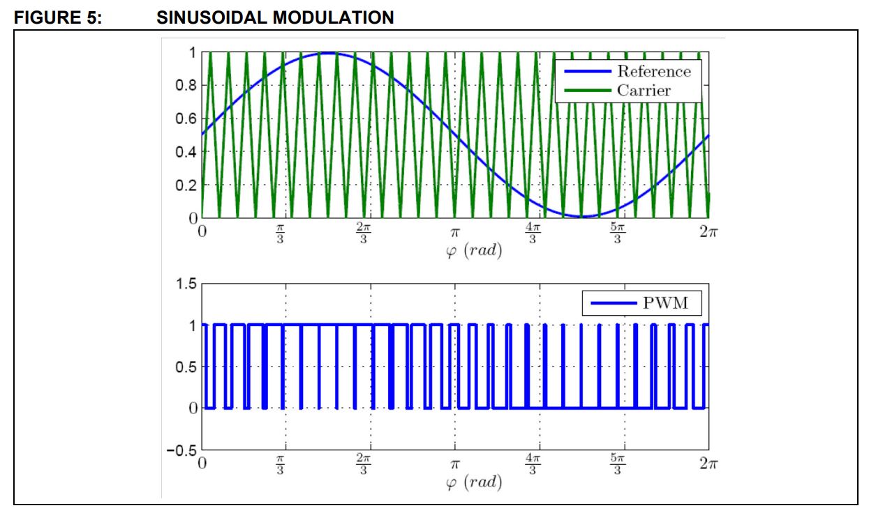
enter image description here The triangle wave is generated by an up-down timer, and the sine wave from a table, multiplied by the modulation index, is then compared at each increment, and the output is then switched when the up/down counter passes that reference value.
enter image description here

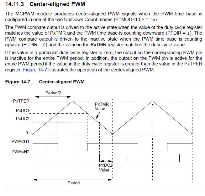
This is from one of Microchip's datasheets, these controllers have PWM generators that have the comparator as part of the module, so there is no need to explicitly do a comparison with the timer value it's a matter of loading the duty cycle register each PWM period with the new value from the sine calculation.

The clock rate and the top value for the counter are determined to give the intended PWM frequency, so will be an odd value unrelated to the PWM amplitude. The duty cycle calculation then needs to be the intended sine value, scaled by the modulation index, and also by the maximum value of the the counter (PTPER on that diagram). The modulation index will come from a control loop trying to maintain the output amplitude responding to the variation in the input and load.

\$\endgroup\$

Your Answer

By clicking “Post Your Answer”, you agree to our terms of service and acknowledge you have read our privacy policy.

Not the answer you're looking for? Browse other questions tagged or ask your own question.