consider this

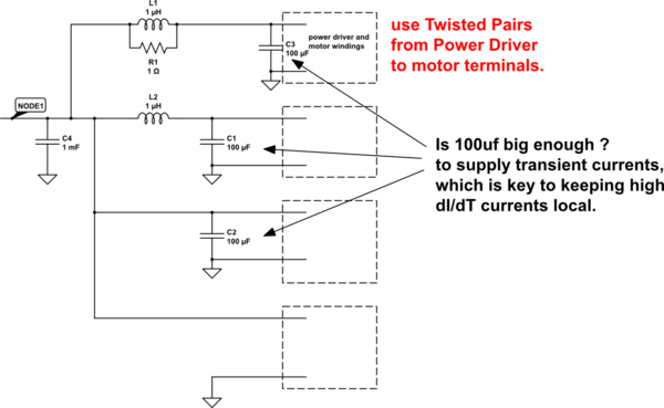
simulate this circuit – Schematic created using CircuitLab
The bottom circuit get the motor currents from the global 1,000uf (1mF); the magnetic fields are enormous, and ringing is uncontrolled. The large loop areas will store lots
of energy, and switching will be slow because the stored energy has to build up and then later dissipated. Because of the large loop area, the field will decay as 1/Distance until you are far away.
The top circuit, with 100uF right at the pins of the Power Driver, has minimal loop area and thus minimal stored energy, thus fastest switching and lowest power dissipation (coolest operation). The 1uH passes very little high frequency to the Global 1,000uF cap, thus there is little radiation of high frequency energy and easiest task in passing ElectroMagnetic Compatibility tests; the 1 Ohm dampens the L+C (1uH and 100uF), tho 0.1 ohm may be more optimal (Rdamp = sqrt(L / C)). Notice the use of Twisted Pair wiring to the motor. You could also used Twisted Pair from the Global 1,000uF to the local 1uH and 100uF. Because of the small loop areas (100 uF to the Power Driver, the magnetic fields will be smaller and will attenuate faster.


