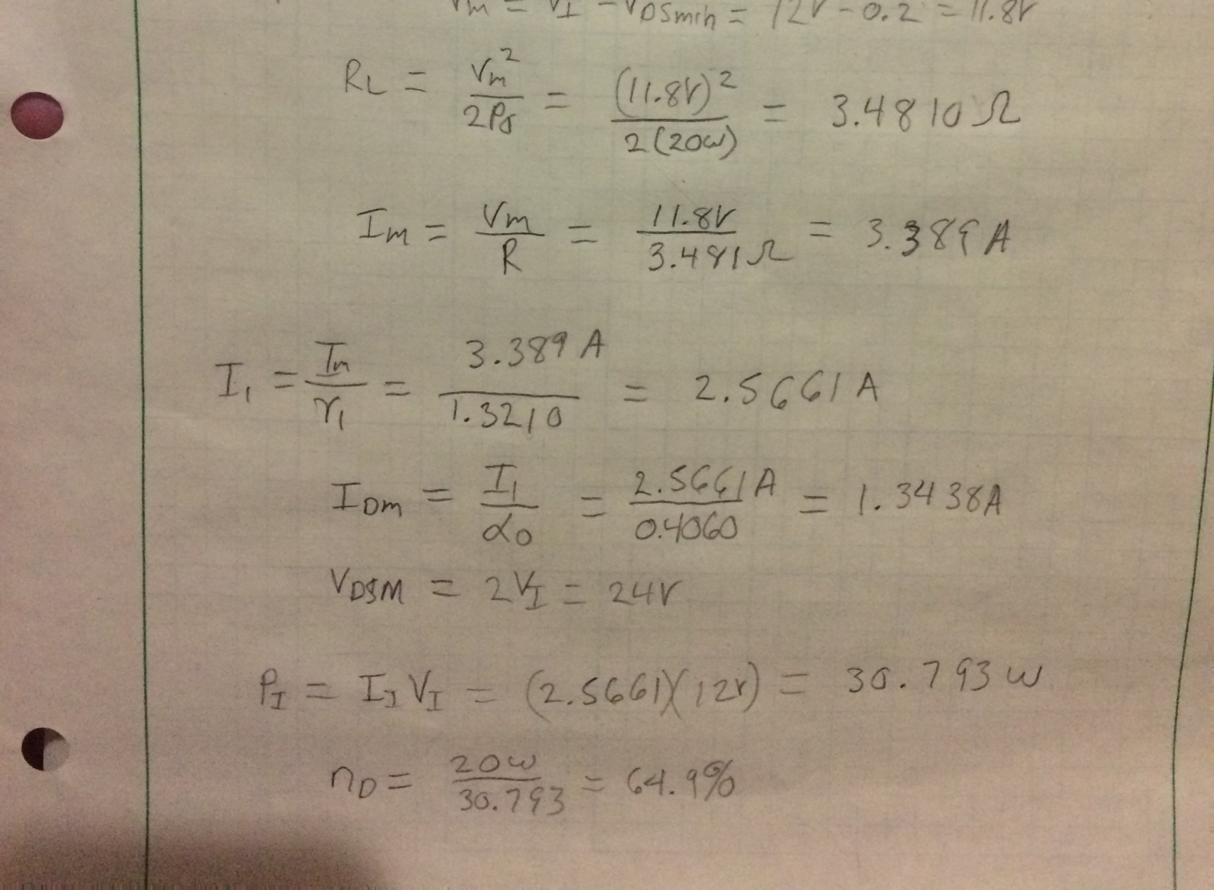
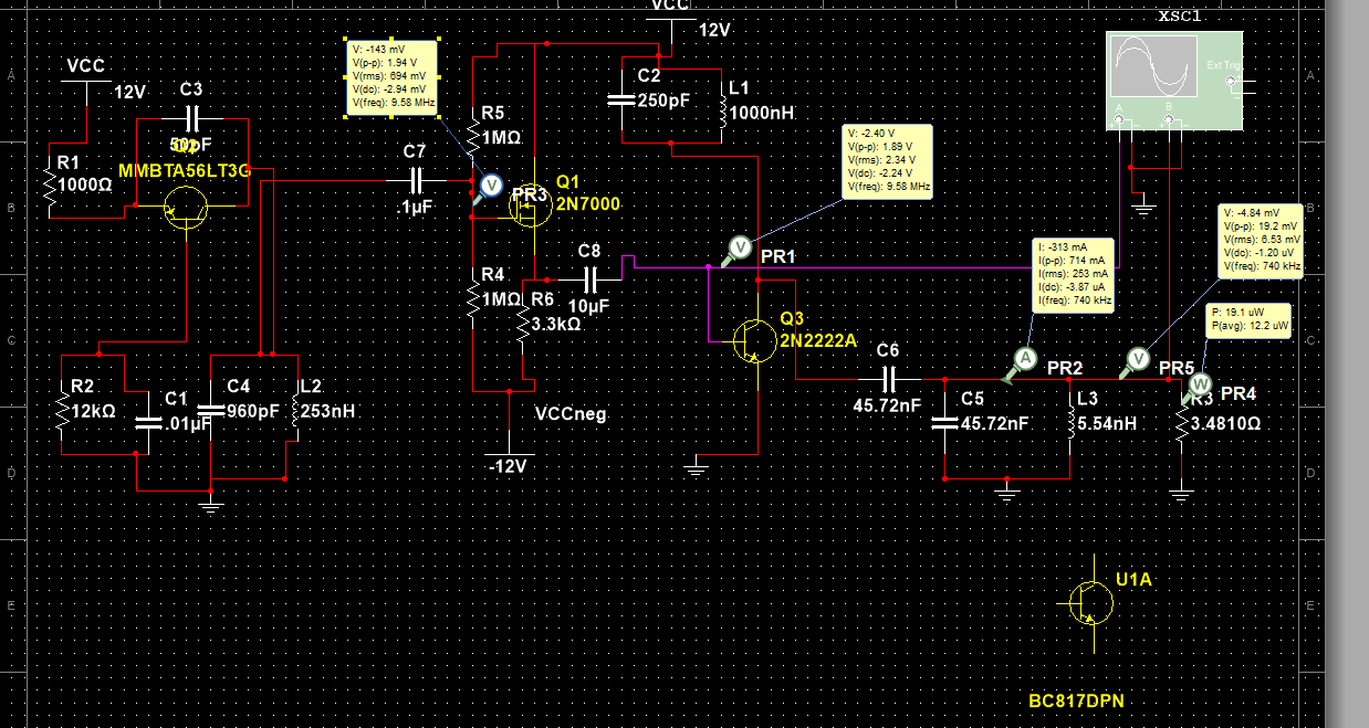
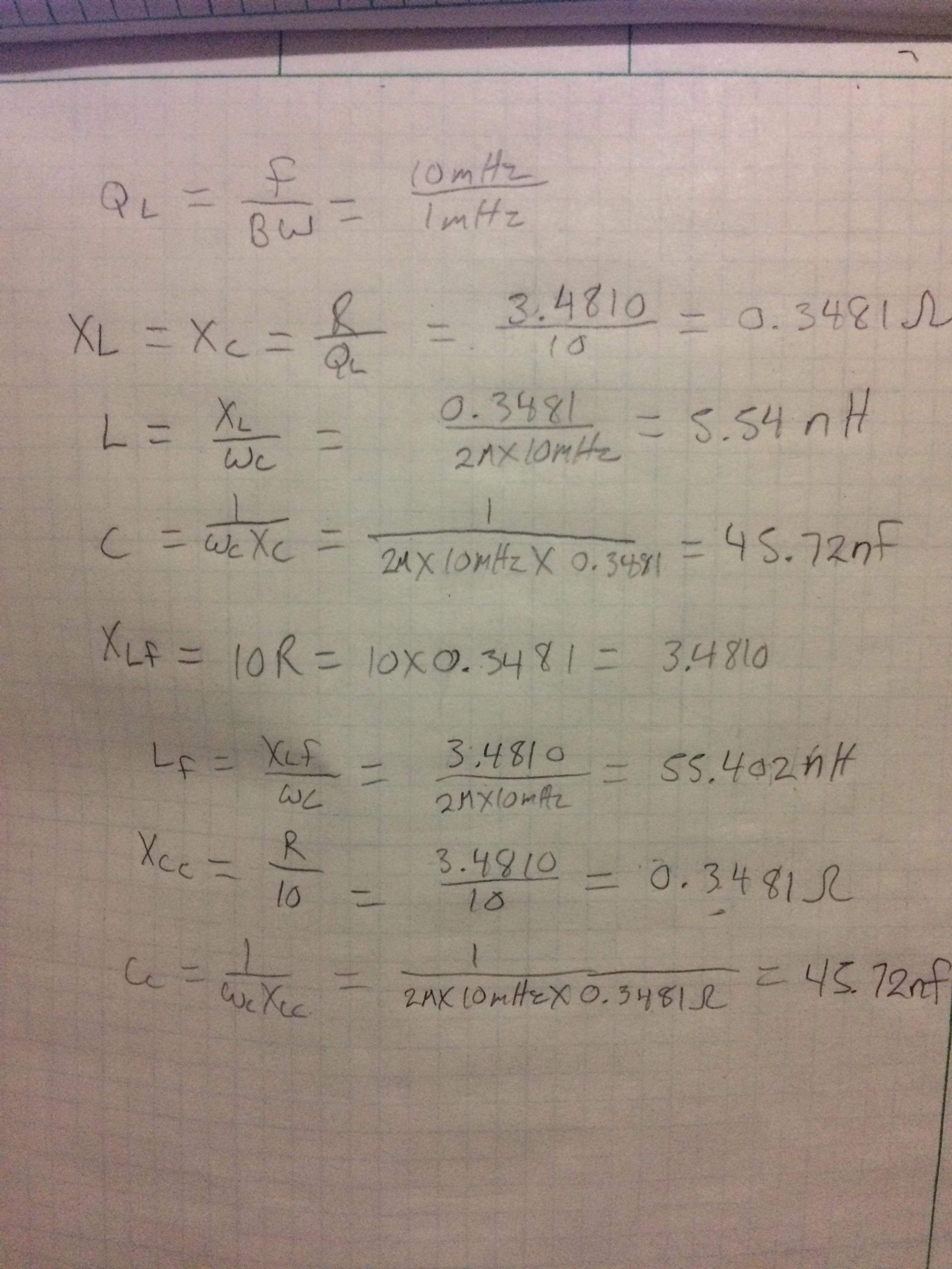
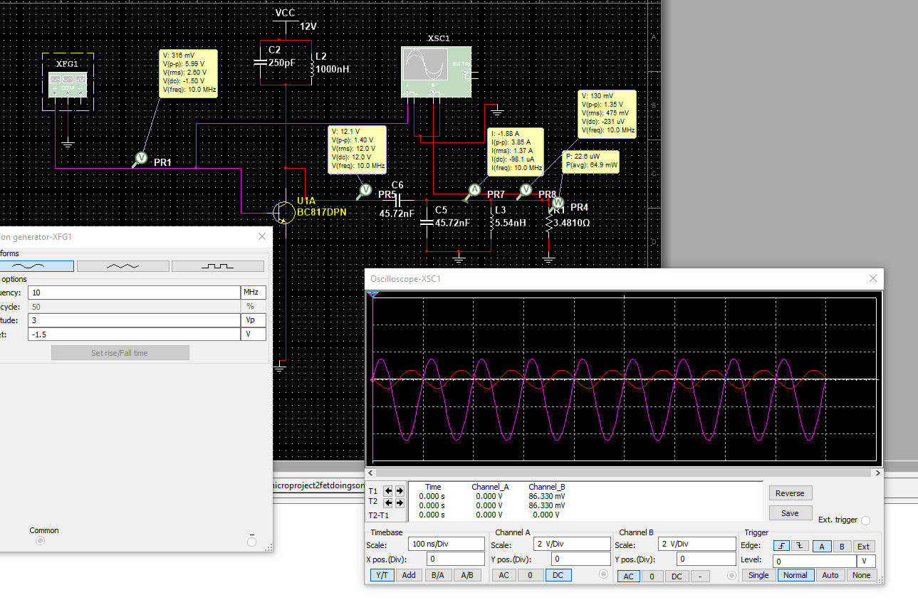
You seem never checked what kind of drive your output circuit (C6 and the rest to the right) needs to have 20W 10MHz AC into the 3,48 Ohm resistor. It's not especially much if the drive were sinusoidal and the frequency is exactly as LC circuit needs. But it isn't. You drive with less than half cycle wide pulses. They must have very high current, for ex. 5A peak. 2N2222 never will make it. In simulation it can stand, but the base current drive seems to be non-existent. Try a pulse generator + a resistor in series at first to drive Q3.
20W into 50 Ohm needs high voltage. You must rise it with transformer if you are going to operate from 12VDC. As well you can have higher DC supply voltage.
You should develop your circuit from the end to left and check with simulations what drive is needed. Start by replacing Q3 with a half of the time conducting switch (+series resistor, say 100 milliohms) and check the output and current need.
Few nanohenry inductances are impractical low - a short wire can have more. You must use higher impedance level and rise the voltage for it.
You have actually 2 resonant circuits in parallel. The will have a strong interaction and the resulted function is complex. Start with one. I bet C2 is meaningless. L1 is needed for DC path, but as well you can have your whole resonant circuit there.
Clever design uses tapped coil (transistor's collector there) to rise the voltage. Then you can have reasonably high inductance and enough voltage for 50 Ohm but still having your low DC supply voltage.
ADD: If you can have higher voltage, say 30...40V you can start with the classic class C amp, which was taken into use about 100 years ago. Today you have a transistor or mosfet instead of a tube.
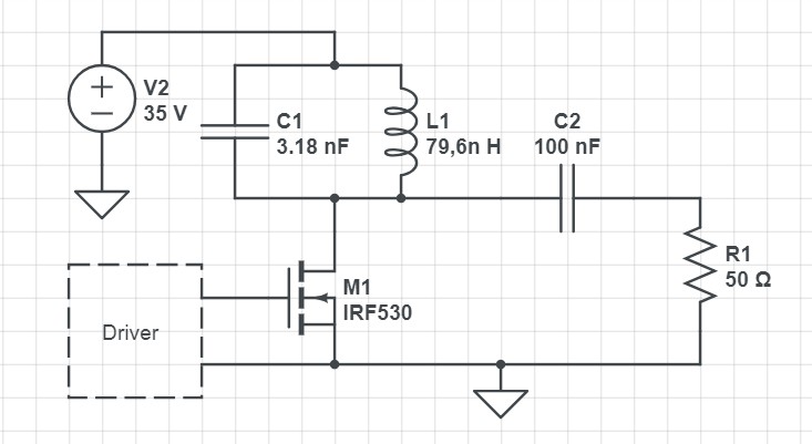
(the mosfet type is random, the editor put it without asking)
A simple resonant circuit can produce at least in oscilloscope sinusoidal looking output when the driver and mosfet do not try too hard. Too hard = restore the oscillation energy too fast into the tank circuit L1C1. Restoring is essentially an attempt to pull the voltage of C1 back to the full supply voltage.
There's about 10 times higher reactive power in the tank than the 20W output to keep the needed restoring injection reasonably small in percents.
Not asked: The current pulse through the mosfet has high peak value and during it there's still substantial loss altough average loss is lower than in class B. Here's an attempt to improve the operation. The idea is taken from flyback power supplies:
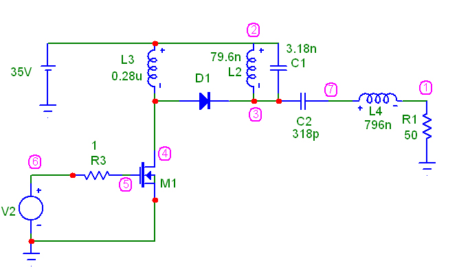
The needed tank energy restoring injection is stored at first to L3. When the mosfet is turned off, the current of L3 makes its way to the tank circuit L2C1.
The waveform in L2C1 is even in oscilloscope clearly distorted. To have more acceptable sinusoidal output, filtering is needed. L4C2 is a simple one for it.
For high efficiency at 10MHz one expects few nanosecond turn off times for M1 and D1. The needed speed is higher than generally available "ultrafast" parts for power supplies have.
(I'm sorry for the lack of the realistic semiconductor part numbers and simulations with them. I have only free demo mode simulation software without part libraries. I use generic parts which operate as ideally as wanted and of course everything with them works perfectly)

 ]
] ]
]