2
\$\begingroup\$

Here's a circuit of an amplifier in the CB configuration: enter image description here
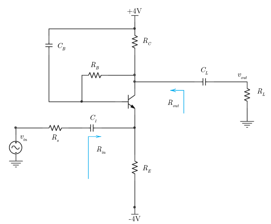
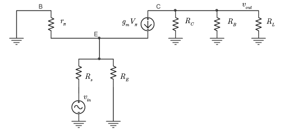
The small-signal equivalent is (using hybrid-pi model)

enter image description here

I want to calculate the input resistance \$R_{in}\$. If I'm not mistaken, the blue arrow in the first picture indicates the direction in which we should look in order to calculate \$R_{in}\$ (looking from the emitter). But if we connect a test source \$v_{x}\$ in parallel to \$R_E\$ we get that $$R_{in} \equiv \frac{v_x}{i_x} = R_E \parallel r_{\pi}$$ (since \$R_E\$ is parallel to \$r_\pi\$).

However according to the answers \$R_{in}=R_E \parallel \frac{r_{\pi}}{\beta + 1}\$ for some reason. I fail to see how is that the case. Any suggestions?

\$\endgroup\$
7
  • \$\begingroup\$ What is the purpose of a test voltage? Answer: To find the current into the test node. Don`t you think that the controlled current source will contribute to the whole current ? (Because a controlling voltage is developped across the left resistance). \$\endgroup\$
    – LvW
    Commented Nov 23, 2018 at 16:27
  • \$\begingroup\$ @LvW - yes, the VCCS will obviously contribute to the current in the E node, but why should it matter? Again, aren't \$R_E\$ and \$r_{\pi}\$ connected in parallel? If yes, then we can replace them with a single resistor \$R_E \parallel r_{\pi}\$. Then the current \$i_x\$ generated by \$v_x\$ will flow through this equivalent resistor. Whether or not \$i_x\$ is influenced by the VCCS shouldn't influence the result in my opinion. \$\endgroup\$
    – grjj3
    Commented Nov 23, 2018 at 16:40
  • \$\begingroup\$ Do the same as I show here electronics.stackexchange.com/questions/407868/… And will find that VCCS contribution changes everything. Additional kept in mind that \$\beta = g_m \cdot r_\pi\$ electronics.stackexchange.com/questions/380593/… \$\endgroup\$
    – G36
    Commented Nov 23, 2018 at 16:55
  • \$\begingroup\$ @G36 - But in that particular example \$R_E\$ and \$R_{\pi}\$ are not in parallel (and the input resistance is calculated as seen from the base and not the emitter) which is why we need to calculate the currents explicitly (and their dependence on \$g_m\$). But in my case the resistors are in parallel, and \$R_{in} \equiv \frac{v_x}{i_x} = R_E \parallel r_{\pi}\$ regardless of how \$i_x\$ depends on \$g_m, V_{\pi}\$ \$\endgroup\$
    – grjj3
    Commented Nov 23, 2018 at 17:41
  • 1
    \$\begingroup\$ But notice that Ic = gmvpi current will load the "test voltage". Because for positive Vin voltage the Vpi voltage will be negative. So gmvpi will be flowing in the opposite direction and load the Vin source. This is why you cannot ignore gm*vpi current. Look at this simplified circuit obrazki.elektroda.pl/5256125900_1542996160.png Also, try to use your intuition and notice that the Vin will affect the emitter current. And the base current is \$I_B = \frac{I_E}{\beta +1}\$. So any change in Ie current will be seen on the base as a \$\frac{I_E}{\beta +1}\$ change. \$\endgroup\$
    – G36
    Commented Nov 23, 2018 at 18:06

1 Answer 1

3
\$\begingroup\$

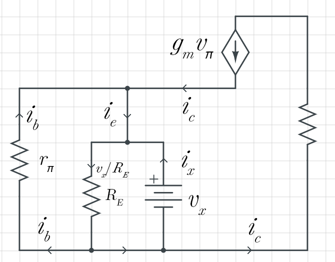
Okay, I think I figured it out.

enter image description here

$$i_x = \frac{v_x}{R_E} - \underbrace{(i_b+i_c)}_{i_e}$$

However \$i_b+i_c = (\beta + 1)i_b\$ and \$i_b = -v_x / r_{\pi}\$

Hence

$$\frac{v_x}{i_x} = \frac{1}{\frac{1}{R_E} + \frac{\beta + 1}{r_\pi}}$$

\$\endgroup\$

Your Answer

By clicking “Post Your Answer”, you agree to our terms of service and acknowledge you have read our privacy policy.

Not the answer you're looking for? Browse other questions tagged or ask your own question.