0
\$\begingroup\$

I'm planning to make some controllers for each of the electrical heaters in my house. The heaters use a pilot wire to control their mode of operation: Pilot wire modes I'm following this project to control the pilot wire: https://web.archive.org/web/20180607082257/http://www.homautomation.org/2015/11/28/pilot-wire-for-electrical-heaters/
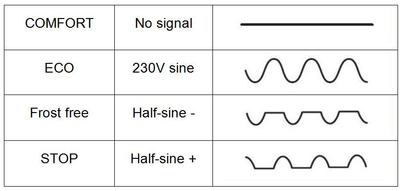
I decided to use a Wemos D1 Mini instead of an Arduino because of size and ease of communicating. Here's my circuit diagram from Fritzing: Pilot wire heater controller
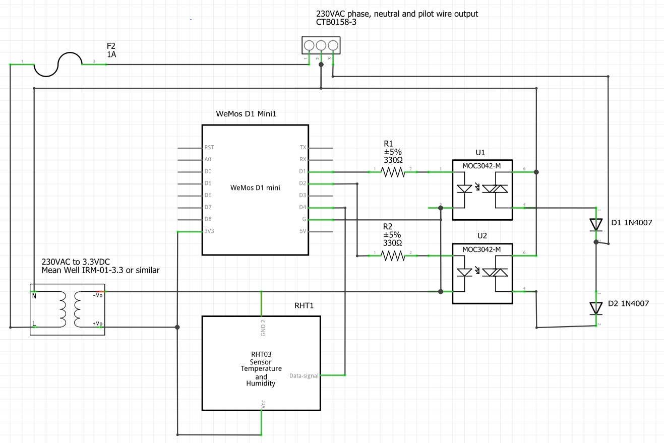
Because the ESP8266 has 3.3V DIO instead of 5V I changed the triacs to MOC3042-M and the resistors to 330 ohms, based on my understanding of their datasheet: https://www.onsemi.com/pub/Collateral/MOC3043M-D.pdf. This isn't the main reason I'm posting, but have I correctly understood this?

My heaters don't have convenient power sockets next to them to be able to power these controllers from a 5V micro-USB charger so I would like to add a 230AC to 3.3VDC converter to the controller which will receive AC power in parallel to the heater. For your info, the heaters only have live and neutral connections, no earth connection. For the AC/DC converter I intend to use a Mean Well IRM-01-3.3 (https://www.meanwell.com/Upload/PDF/IRM-01/IRM-01-SPEC.PDF), Hi-Link HLK-PM03 (http://www.hlktech.net/product_detail.php?ProId=59) or similar - does anyone have any recommendations?

I've read that the ESP8266 can be happily powered directly on the 3.3V pin but I don't know if additional components are needed on the AC or DC side to compensate for noise, surge, etc. I've added a 1A fuse on the live line but I don't know if this is too large or too small. I've read that a varistor should be added to cope with inrush current but I've no idea about size. I read that the Hi-Link converter (actually the 5V version) is very noisy and found a circuit diagram with lots of capacitors and inductors on the AC side to bring the noise down to tolerable levels (https://skippy.org.uk/revisiting-the-hlk-pm01/) is this a suitable/necessary filter for any AC/DC converter I could use?

On the DC side, I've assumed I don't need anything, is this okay?

I will install all the components in a suitable box, probably IP66. These controllers need to be reliable (run for at least two weeks without intervention) and safe (I'm primarily concerned about fire but I also want to preserve what I've made). If anyone spots something I can improve in this regard please tell me.

You can see I've also added a temperature and humidity sensor but that's not relevant to the topic AFAIK. (and FYI it will be mounted outside the box, not inside).

Thanks in advance for your help :)

PS - to give you the full picture, I plan to run Mozilla's webthing-arduino (https://github.com/mozilla-iot/webthing-arduino) on the ESP8266 and have Raspberry Pi running Mozilla's Things Gateway so I can control the heating when I'm out of the house, e.g. turn it on in advance of me returning.

\$\endgroup\$
2
  • \$\begingroup\$ That's the first time I've seen an actual schematic from fritzing! \$\endgroup\$
    – Hearth
    Commented Nov 23, 2018 at 22:33
  • \$\begingroup\$ @Felthry I found a similar project in Fritzing and was going to use it as a base for mine. In the end I didn't but did carry on using Fritzing. It's a bit of a fiddly tool but for me works better than the various webapps that are available. \$\endgroup\$
    – madbilly
    Commented Nov 24, 2018 at 11:44

1 Answer 1

0
\$\begingroup\$

This is an interesting controller method that I have not seen before. It seems reasonably well thought out and your change to ESP8266 seems OK.

I question the trigger current selected for your opto-Triac, and think the 330 Ohm will not work.

If you examine the MOC-30xx datasheet you will notice the last digit selects the sensitivity of the trigger circuit. The MOC-3042 you selected has a maximum trigger current of 10mA. With 330 Ohms series resistor you will only get 5mA at best, so the device may not turn on reliably.

enter image description here

You need to use the MOC-3043 to get this level of sensitivity. Even then I'd suggest the series resistor should be 270 Ohms with the MOC-3043. Note that the original circuit you linked to also has this problem, they were not guaranteed to be able to switch on the MOC-3041, which could require 15mA to turn on under worst case conditions.

Your selection of the MeanWell power supply seems appropriate. I'd be tempted to provide a power supply reset controller to ensure reliable start/reset of the ESP8266. Perhaps a simple unit such as the TI TVL803S would be appropriate.

UPDATE:
The issue of input surge protection is somewhat complex when it comes to very small PS units. Your suggestion of MOV's won't work (they are for limiting surge voltages not limiting initial current surges).
From the MeanWell datasheet you can see the input surge is a maximum of 5A @ 120V and 10A @ 240V, this would seem to indicate they already do have some form of current surge protection built in.

If you want to use an inline fuse, then I'd suggest you need at least a 5A fast blow with a series current limiter. You could use a simple resistor of around 20-33 Ohm, or something like an Anatherm SL10 50002 surge limiting resistor. Note that if you use a surge limiting resistor it won't get hot enough to drop the resistance by much, and so is acting more like a simple series resistor. I would use the SL10 because it's rated for the voltage and help ensure the fuse will blow on a fault.

You can explore the available inrush current limiters on Digikey.

\$\endgroup\$
14
  • \$\begingroup\$ Hi Jack, thanks for your reply. Your point about the trigger current is almost certainly correct. I worked out 330 ohms based on a 3.3V / 330 ohms = 10mA. I'm still not sure what I misunderstood. Thanks for the tip about the reset controller, I'll look into that in more detail. \$\endgroup\$
    – madbilly
    Commented Nov 23, 2018 at 23:56
  • \$\begingroup\$ @madbilly You did not allow for the Vf of the LED in the MOC device. It's not 3.3V you have to work with, only 1.8V. \$\endgroup\$ Commented Nov 24, 2018 at 0:12
  • \$\begingroup\$ Ah! I see now - thank for helping me understand that. \$\endgroup\$
    – madbilly
    Commented Nov 24, 2018 at 0:16
  • \$\begingroup\$ does the fact you've not commented on the AC side fuse or need for a varistor mean you don't think it's necessary? For info, I asked on the ESP8266 forum and they confirmed that the DC side will be fine with the Mean Well PSU without any need for extra components esp8266.com/viewtopic.php?f=160&t=18765 \$\endgroup\$
    – madbilly
    Commented Nov 24, 2018 at 11:53
  • 1
    \$\begingroup\$ The schematic I linked is this one: wiki.wemos.cc/_media/products:d1:sch_d1_mini_v3.0.0.pdf. To me the RST line looks the same as in the one you linked. You are right that there's no controller, but my understanding was that the components they'd already used on the board meant this wasn't necessary (may be ideal, but not necessary). I will try without and if I find problems then I will try adding one. My main concern is about the PSU, I've decided to go with the IRM-02-3.3 with a 600mA output which I'm pretty sure will be sufficient; I changed the pulse withstand resistor to a 7W one. \$\endgroup\$
    – madbilly
    Commented Nov 25, 2018 at 22:46

Your Answer

By clicking “Post Your Answer”, you agree to our terms of service and acknowledge you have read our privacy policy.

Not the answer you're looking for? Browse other questions tagged or ask your own question.