2
\$\begingroup\$

I have a semi-serious hobby project with a couple of friends where we need to charge a pulse operated capacitor rated to around 4kV with 1500nF capacitance.

For this I need a high voltage supply and correct configuration to do the charging. Now I've done this before at around 300V but simulating this process with multisim is nontrivial because in this case I don't know the inner workings of kV-level sources and now I have some questions:

If I were to use an off the shelf high voltage source of around 10kV maximum voltage and 20W power, how will the system react when the source is connected, possibly through appropriate resistor? Someone suggested that exceeding 10kV would immediately break the capacitor as the voltage drop is all seen through the insulation inside the capacitor. I think this is incorrect and the voltage drop will mostly happen inside the HV supply, but I'm not entirely sure.

Let's use this cheap individual as our HV source example: Electrostatic Precipitator Power Supply With Output 300W 30KV

  1. Will an excess voltage (measured at the source) break the capacitor before actually charging it?

  2. If not, how does a typical HV source react to the situation? If connected straight to a capacitor (with effectively zero resistance), will the source just see the connection as a short circuit and promptly break or blow a fuse? Or will it just slowly start to ramp the voltage up, until the external capacitor is at equal voltage to source target (or until the capacitor breaks)?

\$\endgroup\$
6
  • 3
    \$\begingroup\$ Reading your question indicates to me that your knowledge in this field is very limited. As pointed out above, the voltage and energy levels involved are well into the lethal category. My suggestion is to either find someone who is knowledgeable or find another project. \$\endgroup\$
    – Barry
    Commented Nov 24, 2018 at 0:01
  • \$\begingroup\$ that example high voltage source can be turned down to 5kV , but you want 4kV \$\endgroup\$ Commented Nov 24, 2018 at 0:04
  • \$\begingroup\$ There are a number of concerning points about this question that make it look like you really shouldn't be messing with anything this dangerous. Please, find a safer project until you are certain enough of the physics behind this that you don't need to ask. \$\endgroup\$
    – Hearth
    Commented Nov 24, 2018 at 0:22
  • \$\begingroup\$ Well to address safety concerns: Obviously I am no professional electrical engineer. I have a degree in engineering physics though, (which means I tend to solve my lack in hands-on experience by using programs like NI multisim.) Obviously I am aware of the energies involved. To state the question in another way: "As far as typical voltage converters are concerned, what are the characteristics of the terminal end in the context of low-impedance load" \$\endgroup\$
    – Elmore
    Commented Nov 24, 2018 at 0:23
  • 2
    \$\begingroup\$ 1500nF is merely 1.5uF. I think if you hack a bug zapper you will probably get a decent step up converter which will exactly match your need. \$\endgroup\$ Commented Nov 24, 2018 at 0:50

3 Answers 3

1
\$\begingroup\$

I have a semi-serious hobby project with a couple of friends where we need to charge a pulse operated capacitor rated to around 4kV with 1500nF capacitance.

You didn't say exactly what voltage you wanted to charge the capacitor to, but generally speaking you shouldn't go all the way up to the rating if you want the device to be reliable.

For this I need a high voltage supply

You can get a high voltage module from distributors like Digikey or Mouser.

https://www.digikey.com/product-detail/en/xp-power/G30/1470-4014-ND/6802063

https://www.xppower.com/portals/0/pdfs/SF_G_Series.pdf

If I were to use an off the shelf high voltage source of around 10kV maximum voltage and 20W power, how will the system react when the source is connected, possibly through appropriate resistor?

Someone suggested me that the namely excessive 10kV would immediately break the capacitor as the voltage drop is all seen through the insulation inside the capacitor.

If you just put a resistor in series with the capacitor then the capacitor will likely break. If you put the capacitor at the output of a voltage divider then you can lower the voltage enough so that it wont break.

Will an excess voltage (measured at the source) break the capacitor before actually charging it?

No. The capacitor will break once it charges up past its rating. Therefore there must be something to limit the input voltage to the capacitor. For this a voltage divider is a good option.

If not, how does a typical HV source react to the situation? If connected straight to a capacitor (with effectively zero resistance), will the source just see the connection as about short circuit and promptly break or blow a fuse? Or will it just slowly start to ramp the voltage up, until the external capacitor is at equal voltage to source target (or until the capacitor breaks)

That question is impossible to answer in general without knowing the ratings of the components inside the power supply, and what fuses (if any) are used. But I would venture to say that the output will probably just ramp up. Nearly all DC power supplies include some capacitance at their output. You would just be putting a little more in parallel with whatever is already there.

\$\endgroup\$
1
\$\begingroup\$

The example power supply you show has a current limit and a voltage limit: it will limit is output to whichever limit is encountered first.

Into a short-circuit, or a discharged capacitor, it will supply 0 to 10 miliamperes as set by one of the knobs on the end panel.

If you get a supply like that, but that can be set to 4000V instead of the 5000V lower limit of the example device, it will do what you want.

I see your correction from 1500uF to 1.5uF that's now of the approximate scale of the capacitors present in microwave ovens, (slightly larger and slightly higher voltage)

\$\endgroup\$
0
\$\begingroup\$

If you really want to do this, first get a good life insurance policy.

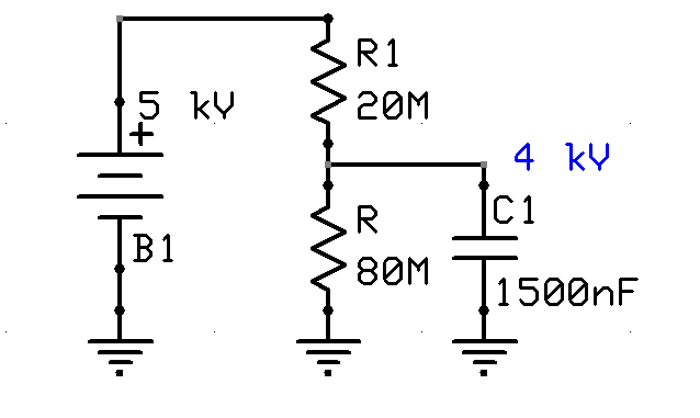
Then it looks like you can have the output set to 5 kV. One simple solution would be to make a resistor divider, maybe this is the only application where resistor dividers are good for:

enter image description here

Power rating should be about 10-40 watts, and the resistors will cost you about $75-$120 each. The cap will be charged in about a minute or two.

However it is not clear what do you mean under "pulse operated" capacitor.

\$\endgroup\$
7
  • \$\begingroup\$ R1 not needed, just set the current limit to 0.05 mA \$\endgroup\$ Commented Nov 24, 2018 at 4:27
  • \$\begingroup\$ @Jasen, no, without R1 the cap will be overcharged to 5kV if the source is not disconnected in time. \$\endgroup\$ Commented Nov 24, 2018 at 19:32
  • \$\begingroup\$ it won\t go past 4kv because with the limit set to 0.05mA, at 4kV all the supply current goes thorigh th 80M. \$\endgroup\$ Commented Nov 24, 2018 at 19:43
  • \$\begingroup\$ @Jasen, I am not so sure. The "specification" says: "1. shortcut protection: when the positive output line and the negative output line are shorted ,the output voltage will be cut off". So, connecting uncharged cap to this PSU will likely cause it to shut down, so nothing will be charged. You need a current limiter, which will be provided by R1 (at 0.25mA). \$\endgroup\$ Commented Nov 24, 2018 at 20:18
  • \$\begingroup\$ that descriotion is not inconsistent with a current limit. In fact all power supplies work that way, it's pretty-much the definition of a short-circuit. \$\endgroup\$ Commented Nov 24, 2018 at 20:25

Your Answer

By clicking “Post Your Answer”, you agree to our terms of service and acknowledge you have read our privacy policy.

Not the answer you're looking for? Browse other questions tagged or ask your own question.