1
\$\begingroup\$

I have been researching how a wheel or crank speed sensor works in vehicles and am having a hard time finding a hard truth.

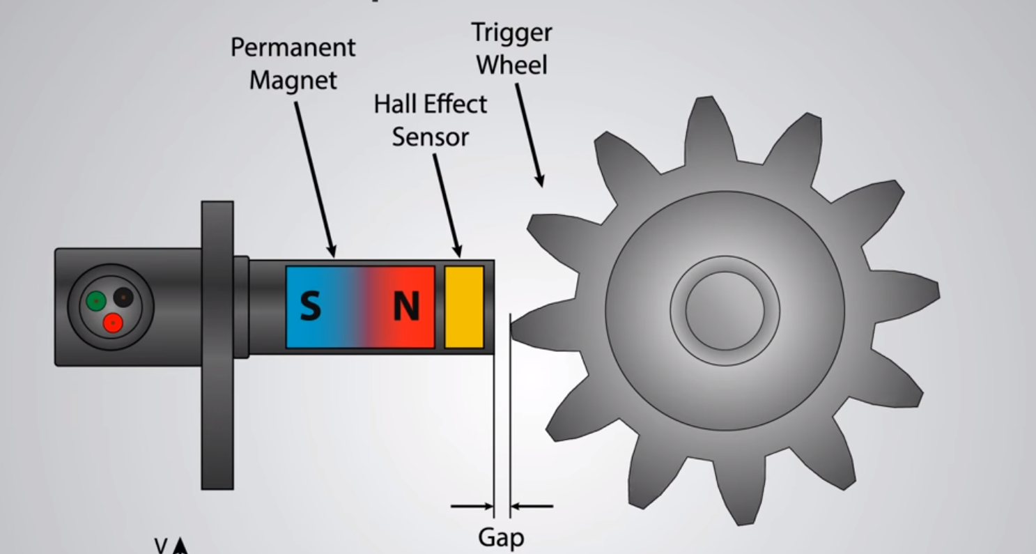
I think I understand how it works simply. That the sensor detects a change in magnetic field and thus produces a hall voltage. The image below makes sense. But internally what is going on? enter image description here

I have seen other images that show a magnet inside the sensor and thus producing a magnetic field. So when the metal rotor or crank comes close to the sensor is that magnetic field reduced or changed enough to then set off the sensor? Therefore, would producing a magnetic field at the end of the sensor produce a signal?

From "How to

From "How To Mechatronics" Youtube Channel.

Ultimately, what is the magnetic field around the sensor doing that triggers the sensor?

\$\endgroup\$
4
  • \$\begingroup\$ The first image shows the magnetic-to-electrical conversion (voltage generated due to the hall effect). Is that not a sufficient explanation? Anything deeper probably belongs at Physics.SE. If you're wondering how the signal depicted in the first image can be used to create a signal (let's say a steady-state voltage corresponding to rotor speed), look up "frequency-to-voltage converter" or "integrator circuit". \$\endgroup\$
    – Shamtam
    Commented Nov 26, 2018 at 18:40
  • 2
    \$\begingroup\$ Do you understand the Hall effect to begin with? \$\endgroup\$
    – Dave Tweed
    Commented Nov 26, 2018 at 18:41
  • \$\begingroup\$ At least I think I do and have done quite a bit of reading on it. But I was curious about how the magnet and the rotor interact to change the field to produce a signal. \$\endgroup\$ Commented Nov 26, 2018 at 18:45
  • 1
    \$\begingroup\$ are you sure that you are talking about a solid state hall effect sensor? ... could the sensor actually be a reluctance sensor that uses a coil? \$\endgroup\$
    – jsotola
    Commented Nov 26, 2018 at 19:44

3 Answers 3

5
\$\begingroup\$

But I was curious about how the magnet and the rotor interact to change the field to produce a signal.

This type of sensor is known as a "variable reluctance sensor".

Magnetic fields form loops, and you can think of the path that the field follows as a "magnetic circuit". The circuit includes a permanent magent (equivalent to a battery) and materials with varying amounts of reluctance (equivalent to resistance). Steel has low reluctance, while air has very high reluctance. The field intensity is equivalent to current.

In this case, the circuit includes the magnet, the gear, and the other steel structures that hold them relative to each other. As the toothed gear rotates, it periodically increases and reduces the air gap in the magnetic circuit, which directly decreases and increases, respectively, the field intensity passing through the Hall sensor.

\$\endgroup\$
0
1
\$\begingroup\$

The magnetic field changes a tiny bit each time a tooth on the gear goes by.

This causes a tiny change in the voltage across the hall sensor.

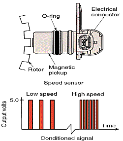
The tiny change in voltage is amplified, then fed through a comparator that outputs a nice square edged signal each time it detects a tooth.

You really ought to take a look at how hall effect sensors work.

How it works is fascinating, and the extreme small size of the effect (and what it takes to make a simple, reliable, easy to use sensor) ought to make you appreciate the ingenuity of those unsung engineers who make it "just work."

You have basically a physics lab full of precision instruments packed into one little chip.

The basic effect is caused by the magnet deflecting the electrons moving in one direction through a conductor. The magetic field makes them take a slightly curved path which results in more electrons flowing on side side. The result is a voltage across the conductor perpendicular to the flow of current. (Paraphrased from Wikipedia.)


Pretty much any (relatively) sudden change in the magnetic field will cause a pulse in the output.

If you wire up such a sensor so that it can work, you can observe the output with an oscilloscope.

Waving a screwdriver tip across the face of the sensor will cause pulses to appear.

How far the screwdriver (or other magnetic object) can be from the sensor depends on how strong the magnet is, and how sensitive the hall sensor is - which is related to how thin the sensor's internal conductor is. Thinner is more sensitive.

The original experiments used gold leaf as the conductor in the sensor, and fairly high currents to get a high enough voltage to be detectable.
\$\endgroup\$
-1
\$\begingroup\$

There are hall sensors with and without magnets inside. The hall sensor detects the magnetic field and therefore detects the permanent magnet located inside the sensor. When a ferrous object, such as a steel gear tooth comes near to the sensor, it causes more of the magnetic flux lines of the permanent magnet to pass through the coil, essentially causing the agent to act more strongly on the hall sensor. This is what is picked up by the Hall sensor.

See the following link to find out more The Sensor Shack - Hall effect sensors

\$\endgroup\$
0

Your Answer

By clicking “Post Your Answer”, you agree to our terms of service and acknowledge you have read our privacy policy.

Not the answer you're looking for? Browse other questions tagged or ask your own question.