I want to implement several IIR filters on an FPGA, using VHDL. The filters is for audio. I start out by implementing a single filter with the following transfer function:
$$H_1(z)=\frac{304 -304z^{-2}}{16384 - 32109z^{-1} + 16076z^{-2}}$$
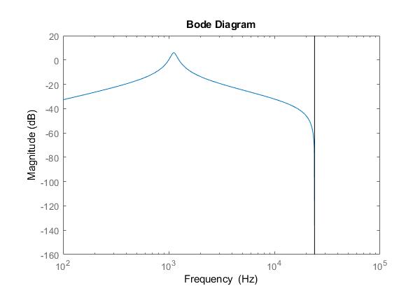
This transfer function should have the following frequency response:
And should be possible to implement with the following difference equation:
$$16384\cdot y[n] = 304\cdot x[n] -304 \cdot x[n-2] +32109 \cdot y[n-1] - 16076\cdot y[n-2]$$
I have tried implementing the filter with the two follwing pieces of code:
library ieee;
use ieee.std_logic_1164.all;
use IEEE.numeric_std.all;

entity FILTER is
    port (
    GPIO                    : inout std_logic_vector(35 downto 0); --I/O
    CLK_50                  : inout std_logic; --50 MHz clock
    CLK                     : in  std_logic;   --3.072 MHz clock
    CHANNEL                 : in std_logic;    --Channel select 48 kHz
    data_left_in            : in std_logic_vector(15 downto 0);
    data_right_in           : in std_logic_vector(15 downto 0);
    data_left_out           : out std_logic_vector(15 downto 0);
    data_right_out          : out std_logic_vector(15 downto 0)
    );
end FILTER;

architecture behave of FILTER is
    signal input_left       : signed (15 downto 0);
    signal input_right      : signed (15 downto 0);
    signal output_left      : signed (15 downto 0);
    signal output_right     : signed (15 downto 0);

    signal i_0_left : signed (15 downto 0);
    signal i_0_right : signed (15 downto 0);

    COMPONENT filter_class
    port (
    GPIO                    : inout std_logic_vector(35 downto 0); --I/O
    CLK_50                  : inout std_logic;   --50 MHz clock
    CLK                     : in  std_logic;     --Channel select 48 kHz
    sample                  : in signed (15 downto 0); --filter input
    sample_filtered         : inout signed (15 downto 0); --filter output

    b00                     : in integer range -32768 to 32767; --filter coefficients
    b01                     : in integer range -32768 to 32767;
    b02                     : in integer range -32768 to 32767;
    a01                     : in integer range -32768 to 32767;
    a02                     : in integer range -32768 to 32767;

    scaling                 : in integer range 0 to 16; --scaling for fixed point

    gain                    : in integer range -32768 to 32767;
    gain_scaling            : in integer range 0 to 15
    );
    END COMPONENT;

    begin

    Filt_0_r        : filter_class  PORT MAP (GPIO(35 downto 0), CLK_50, NOT CHANNEL, input_right, i_0_right , 16384, 0, 0, 0, 0, 14, 1, 0); --no filtering
    Filt_0_l        : filter_class  PORT MAP (GPIO(35 downto 0), CLK_50, CHANNEL, input_left, i_0_left, 16384, 0, -16384, -32113, 16081, 14, 1, 0); --filter with tf H1(z)

    process (CHANNEL) --send output to DAC
    begin
        if RISING_EDGE(CHANNEL) then
            input_left <= signed(data_left_in);
            data_left_out <= std_logic_vector(i_0_left);
        end if;
        if FALLING_EDGE(CHANNEL) then
            input_right <= signed(data_right_in);
            data_right_out <= std_logic_vector(i_0_right);
        end if;
    end process;
end behave;
and
    library ieee;
use ieee.std_logic_1164.all;
use IEEE.numeric_std.all;

entity filter_class is
    port (
    GPIO                    : inout std_logic_vector(35 downto 0); --I/O
    CLK_50                  : inout std_logic;   --50 MHz clock
    CLK                     : in  std_logic;     --Channel select 48 kHz
    sample                  : in signed (15 downto 0); --filter input
    sample_filtered         : inout signed (15 downto 0); --filter output

    b00                     : in integer range -32768 to 32767; --filter coefficients
    b01                     : in integer range -32768 to 32767;
    b02                     : in integer range -32768 to 32767;
    a01                     : in integer range -32768 to 32767;
    a02                     : in integer range -32768 to 32767;

    scaling                 : in integer range 0 to 16; --scaling for fixed point

    gain                    : in integer range -32768 to 32767;
    gain_scaling            : in integer range 0 to 15
    );
end filter_class;

architecture behave of filter_class is

    TYPE multipliers IS ARRAY (NATURAL RANGE <>) OF SIGNED (17 DOWNTO 0);
    TYPE result IS ARRAY (NATURAL RANGE <>) OF SIGNED (35 DOWNTO 0);

    signal y00 : signed (15 downto 0);

    signal sum_1 : signed (37 downto 0);

    signal samp : multipliers(0 to 5);
    signal coef : multipliers(0 to 5);
    signal resu : result(0 to 5);

    signal channel_state : std_logic;

begin

    process (CLK_50) --calculate filter
        variable cnt : integer := 0;
        variable flag : std_logic := '0';
    begin
        if RISING_EDGE(CLK_50) then

            channel_state <= CLK;

            if channel_state = '0' AND CLK = '1' then --if new sample

                flag := '1';

            elsif flag = '1' then --calculate

                cnt := cnt + 1;

                if cnt = 4 then --save coefficients in array

                    coef(0) <= to_signed(b00,18);
                    coef(1) <= to_signed(b01,18);
                    coef(2) <= to_signed(b02,18);
                    coef(3) <= to_signed(-a01,18);
                    coef(4) <= to_signed(-a02,18);

                    coef(5) <= to_signed(gain,18);

                    samp(5) <= resize(y00, 18);

                end if;

                if cnt = 29 then --reset count if all done
                    cnt := 0;
                    flag := '0';
                elsif cnt > 5 AND cnt < 12 then
                    resu(cnt - 6) <= coef(cnt - 6) * samp(cnt - 6); --multiply coefficients and sample, and gain
                elsif cnt = 12 then
                    sum_1 <= to_signed(0, 38); --reset filter sum
                elsif cnt > 12 then
                    sum_1 <= sum_1 + resu(cnt - 8); --calculate sum
                end if;
            end if;
        end if;
    end process;

    process (CLK)
        variable y00_temp_1 : signed (37 downto 0);
        variable y00_temp_2 : signed (37 downto 0);

        variable sample_filtered_temp_1 : signed (35 downto 0);
    begin
        if RISING_EDGE(CLK) then
            --delay line
            samp(2) <= samp(1);
            samp(1) <= samp(0);
            samp(0) <= resize(sample, 18);

            samp(4) <= samp(3);
            samp(3) <= resize(y00, 18);
            y00_temp_1 := sum_1; --set output
            y00_temp_2 := shift_right(y00_temp_1, scaling); --divide by 2^14 for scaling
            y00 <= y00_temp_2 (15 downto 0); --filter output

            sample_filtered_temp_1 := shift_right(resu(5), gain_scaling); filter gain scaling
            sample_filtered <= sample_filtered_temp_1 (15 downto 0); --filter output * gain
        end if;
    end process;
end behave;
This is my first VHDL code, and errors may be many.
With this code the filter do not work.
The right channel filter works (just passthrough), and give 1/1 output.
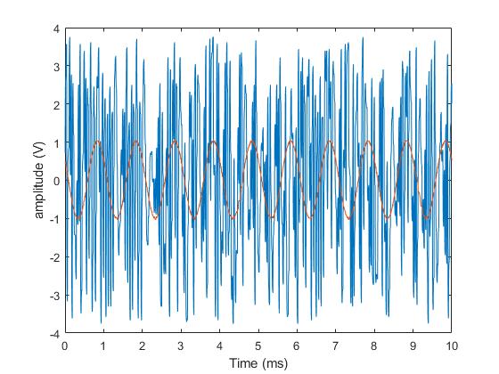
The left filter does not works and gives only noise, independent of input signal. With a inout signal of 1 kHz, and 1 V amplitude, the output signal can be seen:
The red waveform is the output of the right filter, the blue is the left filter.
If using a lower scaling factor, ex. 2^15 or 2^16, the output will look different. At 2^16, the output will be 0. Because of this i suspect that the problem is some kind of wrong truncation of the signal.
Does anyone have an idea of what i am doing wrong with the filter?


